Making a Very Small Video Game
I’m making a very simple Pong Console. It’s based on an ATTiny microcontroller and not much more.
The goal was to make it as small as I can. Technically it is surely possible to make it even smaller, but I don’t have much experience yet with SMD soldering, and I wanted to keep it big enough so I can confidently hand-solder everything.
The idea came from my realization that I wanted to improve my practical understanding of timing in the milliseconds and microseconds range. Bit-banging a video signal sounded like a fun idea to practice.
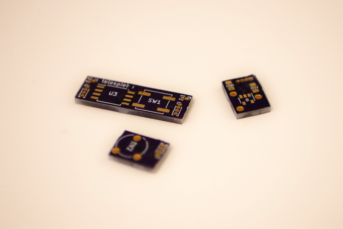
I designed the PCB using KiCad and had it manufacured at OSH Park. As mentioned before, I handsoldered all the components, although in the future, for similar projects I should probably try reflow soldering.
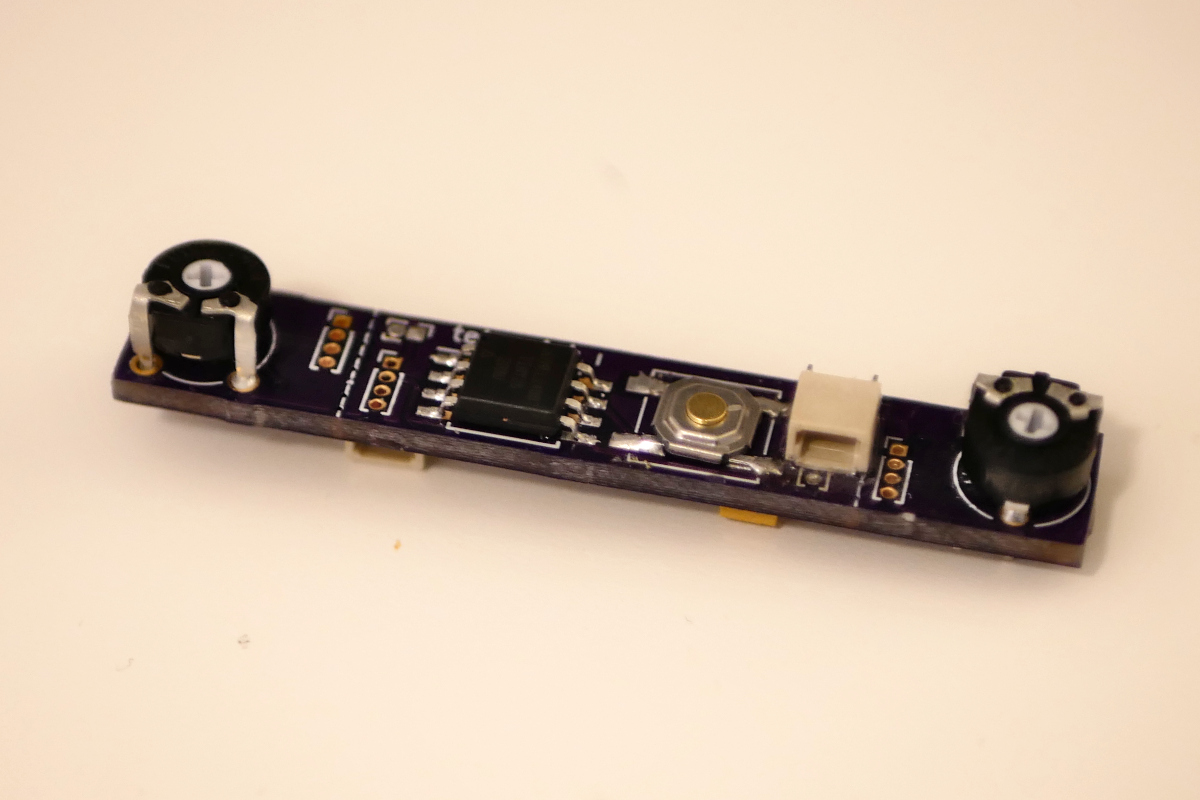
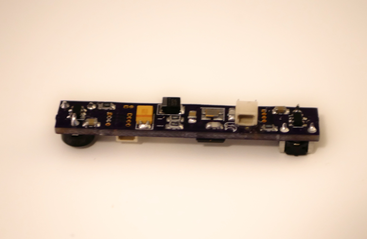
Most space on the top of the board is taken up by the ATtiny 25 and the inputs - one push button and two potentiometers. All the other components, including the 16MHz oscillator, are mounted on the bottom.
Generating Video Signals
The video signal is generated using two output pins, PB0 and PB1, using two resistors. I used the same concept as the Arduino TV Out: using two pins to generate the three distinct levels needed for the video signals. The Arduino uses a more powerful microcontroller, so it can do much more sophisticated graphics than my ATTiny.
Together with the 75Ω load the monitor puts on the line, we get the following voltage levels.
| PB0 | PB1 | Output | Used as |
|---|---|---|---|
| Low | Low | 0V | Sync pulse |
| Low | High | 0.3V | Normal level (dark parts of screen) |
| High | Low | 0.64V | Unused (could be used for half-bright video) |
| High | High | 0.95V | Video on (bright parts of screen) |
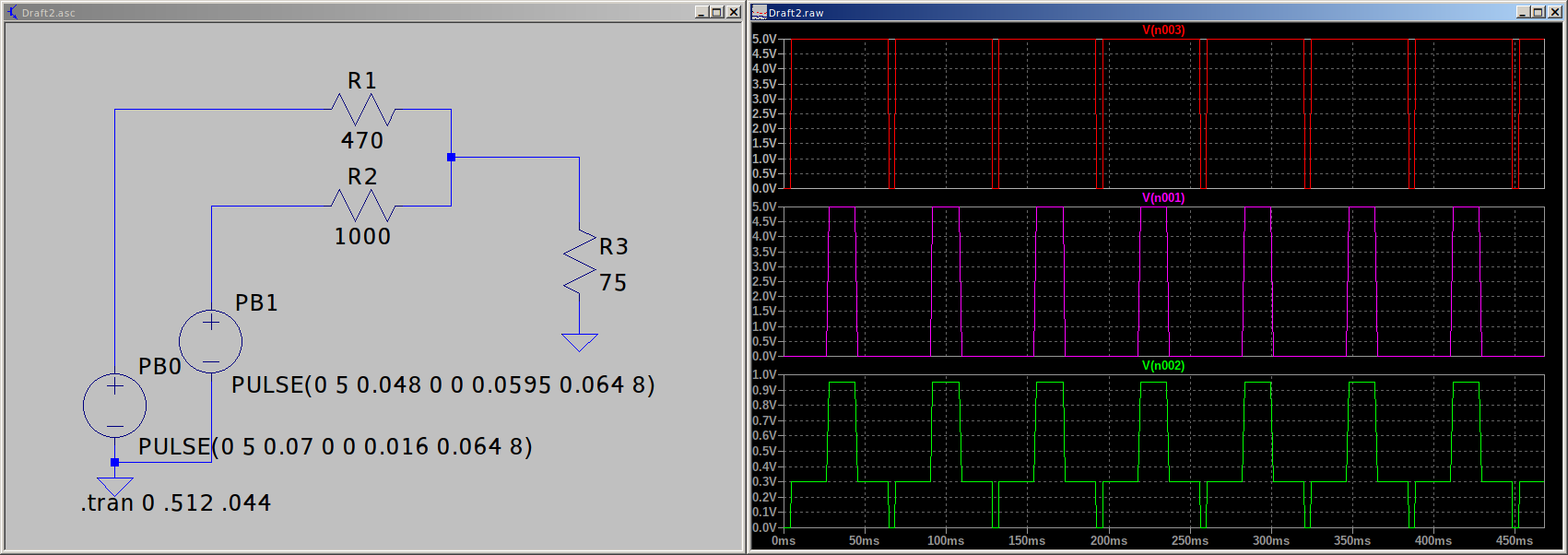
So the circuit and signal look something like this:
 (click to zoom in)
The green plot in the image above shows the video signal that is generated. Each repetition of the pattern is a line in the video image – the low-going pulses are the horizontal synchronization pulses, and the larger high-going pulses would be a bright area in the center of the screen.
This is achieved in the following way:
The ATTiny’s timer-counters count from one to 255 on every line the monitor draws.
PB1 (the red trace in the image above) is normally high, and pulses low to generate a H-sync pulse. This is done using the ATTiny’s PWM facilities.
PB0 (the purple trace) handles the actual graphics. Since the PWM generator can only toggle the pin on one variable compare match (the other always being on counter reset), graphics are handled by an interrupt handler. Depending on which line of the screen we’re on, the compare register is set to a specific point, and a “drawing routine” is selected to be called on compare match.
On the off-screen lines, the interrupt handlers change the timer settings to make the vertical sync happen.
All this together amounts to what a video monitor or old television expects – a Video-Blank-Sync (VBS) signal (in German: Bild-Austast-Synchron-Signal).
How wide each element of the graphics should be is determined in the “drawing routines” either by counting cycles or by repeatedly checking the counter register. Like in most video games, reading inputs and updating the positions of all the objects is done during the horizontal blanking of the monitor.
Reading the Inputs
The player input consists of two potentiometers and a start button. But we only have one input pin left to read two analog inputs and a button. This is done using the following trick:
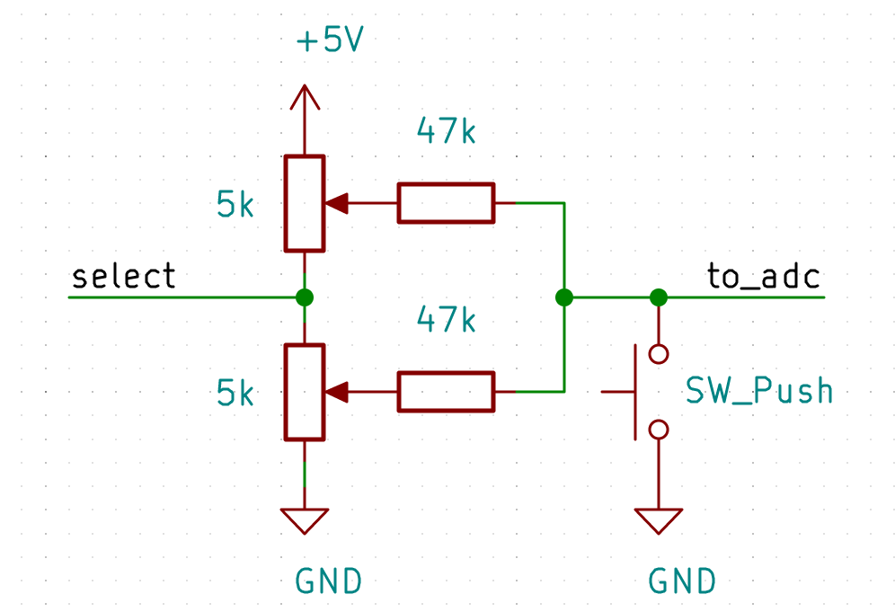
The select input of this circuit is actually the video output of the ATTiny, because there are no other IO pins left. When it is high, the bottom potentiometer can be read. Depending on the position of the wiper, 2.5 - 5V are present on the ADC input. When the select pin is low, the top potentiometer can be read (range 0 - 2.5V). When the button is pushed, the input reads 0 regardless of the state of the input. Since the input is also connected to the video output (again, not many IO pins on this microcontroller), switching on that pin causes a white line to appear on screen. However, the input is only read once per video fram, and I do it after the playfield has been drawn, so the line appears on the very bottom of the screen. and doesn’t interfere with the game. In fact, on most “old-school” CRT monitors it should even be off-screen completely.
The scematic above is actually a bit simplified. In reality, the load of the monitor (75Ω) pulls the voltage of the input (remember, it’s also the video output) a bit low, which makes the two supposedly independent potentiometers interfere with each other a little bit. I used two single schmitt-trigger inverters (SN74LVC1G14) to buffer the select signal. Of course that now inverts the selection of player 1 / 2, but that’s easily fixed in software.
Why two?
Well, the ends of the circuit board are perforated and can be broken off, and there are places to add connectors, so you can make the “console” have detachable controllers! Each controller has its own buffer for the potentiometer select signal.
Game Logic
It’s like Pong, but vertically. I had to make it vertical - playing the ball from top to bottom instead of left to right - because I couldn’t make it draw multiple objects close together on the same screen line without glitches.
The further away from the center of the paddle the ball hits, the more horizontal speed it picks up, so you can hit it at an angle and confuse your opponent. The horizontal speed is additive - multiple off-center hits make the ball move faster and faster sideways, which together with the vertical movement makes it so the angle becomes steeper and steeper. And because it’s additive, you have to hit it with the other side of the paddle several times to compensate.
I also made the ball go a little faster (vertically) with each hit, so the better the players are, the longer they can keep the ball in play.
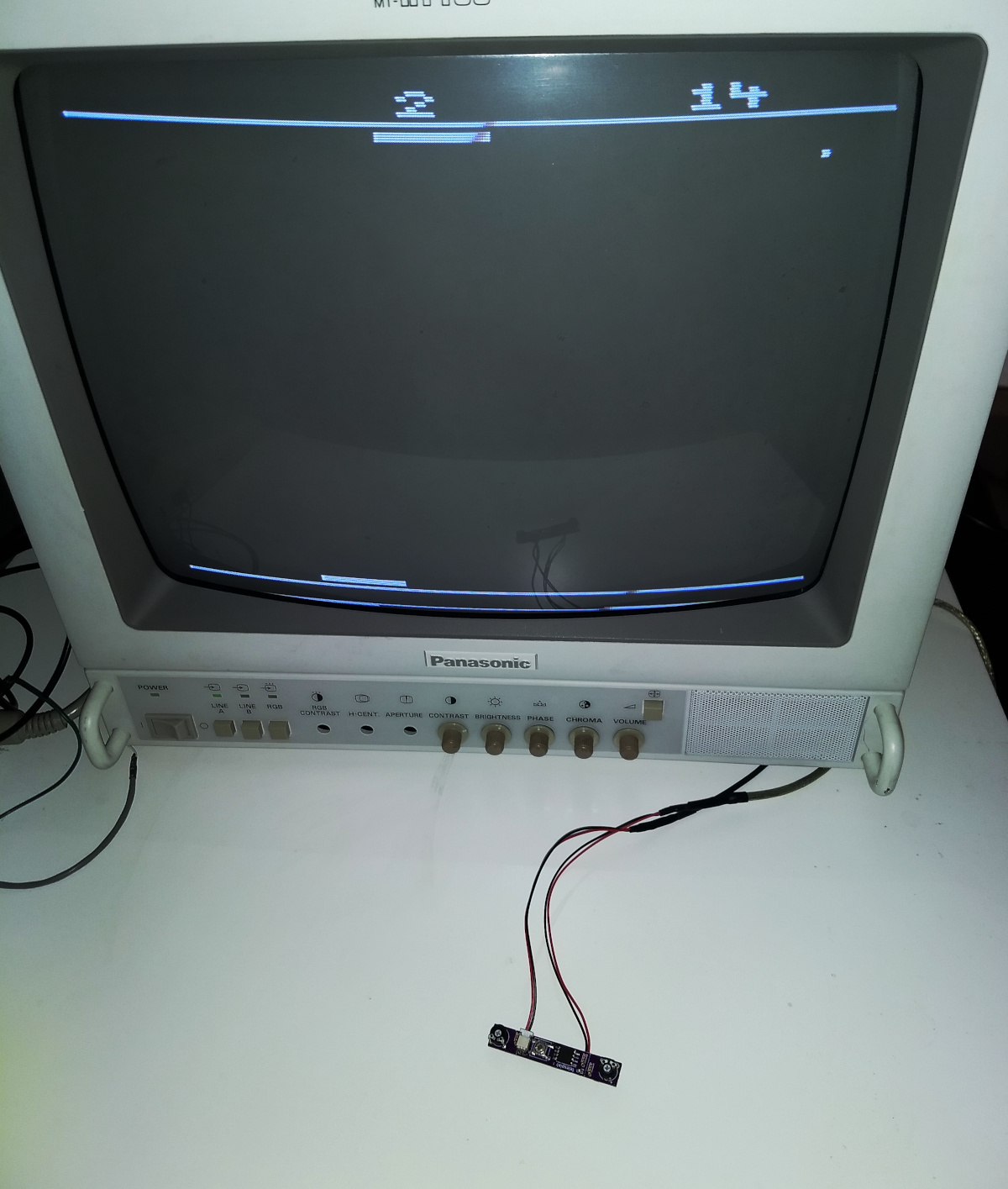
Like in Pong, when a player misses the ball, a point is scored for the other player, and the ball resets to the center. Once one player reaches 15 points, the game ends. It can be restarted at 0 points by pushing the button. The score limit is 15, because I only made the graphics for the numbers 0 to 15 - limited program memory space and all.
For easier gameplay, I might also have to add some handles, like small wooden pegs, to the potentiometers.
Learn More (and watch the video)
I gave a talk about how I made this game at Chaos inKL.. You can watch the recording (in German) here
…or skip ahead to 39:00 if you just want to see some gameplay footage.