The Software
I was recently asked on Twitter how I managed to get 16 PWM channels out of an ATMega 168. This microcontroller only has 3 hardware PWM channels, so there’s a little trick involved using timer interrupts.
Here’s the timer setup routine, which is called at bootup:
void setup_timer() {
  TCCR0A |= (1 << WGM00) | (1 << WGM01);
  TCCR0B |= (1 << CS02) | (1 << WGM02);
  TIMSK0 |= (1 << TOIE0);
  OCR0A = 1;
}
Nothing magical so far: the three WGM bits are set, so that the timer is reset once the counter reaches the value in register OCRA, and then the timer overflow interrupt is fired. The CS bits are set so that the input of the timer is the main clock divided by 256. This frequency was chosen by experiment, timed so that the timer interrupt routine can comfortably execute and still allow for the main program to run in between timer interrupts. The timer overflow interrupt is enabled by setting TOIE0. Lastly, the output compare register OCR0A is preloaded with the value 1.
Here’s the next bit of code, the timer interrupt routine.
ISR(TIMER0_OVF_vect) {
  cli();
  pwm_bit();
  sei();
}

void pwm_bit() {
  static uint8_t index = 0;
  index = (index + 1) % 8;

  // Set timer value for the *next* bit (because OCR0A updates at BOTTOM)
  OCR0A = (0x01 << (index + 1) % 8) - 1;

  PORTB = bits_pb[index];
  PORTC = bits_pc[index];
  PORTD = bits_pd[index];
}
The interrupt handler itself just calls pwm_bit, and there the the interesting part happens. We’re using 8 bit PWM here, so we have an index that counts up from 0 to 7. First thing we do is update OCR0A for the next round. The formula calculates the new compare value so that the register cycles through the values 0, 1, 3, 7, 15, 31, 63, 127. This way, the timer interrupt does not fire at a constant rate, but at 1, 2, 4, … cycles (since the value 0 is also held in the timer counter register for one cycle).
Now we have the powers of two, i.e. the value of each individual bit, encoded in the length of time between timer interrupts - the least significant bit is worth one cycle, the next one two, and so on, until the last one which is worth 128 cycles. We just need to shift out the bits of each PWM channel to the corresponding output pins. The whole 16 channels do not fit on a single port of the AVR. In fact, because we also use the serial port of the ATMega, the 16 channels need to be spread out across three different ports. Another routine - we’ll have a look at it in a second - has already preloaded the PWM bits into three arrays of bytes.
Each array holds data for one port, laid out so that each byte contains the data to be emitted at a paricular time. For example, the byte in bits_pb[0] contains all the least significant bits of the PWM channels connected to PORTB. bits_pb[1] contains the next bits, and so on. bits_pb[7] consequently holds the most significant bits of the channels.
Of course, in this setup the PWM can switch multiple times per cycle. For example, here is what the output looks like for a value of 170, which conveniently is 10101010 in binary:
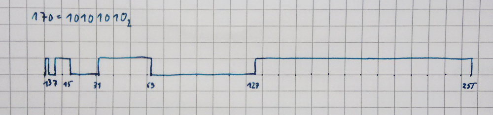
The signal stays low for 1 cycle (least significant bit is 0), then goes high for 2 cycles, low again for four cycles, high for 8 cycles, and so on. So it is not a clean PWM signal with a fixed frequency, but it gets the job done, because the capacitors connected to the outputs take care of the smoothing. But even without smoothing it is usable: I’m using the same scheme for 3 PWM channels in the lys project, where the outputs of the ATMega are connected to MOSFETs driving the LEDs.
Now the last bit of the code is where the input is transformed to the bit patterns for the PWM. The input is an array of numbers in the range [0 .. 255]. Here’s the code that transforms it into the bit patterns for the ports:
void pwm_set(const uint8_t* val) {
  for (uint8_t bit_index = 0; bit_index < 8; bit_index++) {
    uint8_t mask = 1 << bit_index;

    // Values 0..5 to PORTC[0..5].
    for (uint8_t val_index = 0; val_index < 6; val_index++) {
      if (val[val_index] & mask)
        bits_pc[bit_index] |= (1 << val_index);
      else
        bits_pc[bit_index] &= ~(1 << val_index);
    }

    // Values 6..8 to PORTB[0..2].
    for (uint8_t val_index = 0; val_index < 3; val_index++) {
      if (val[val_index + 6] & mask)
        bits_pb[bit_index] |= (1 << val_index);
      else
        bits_pb[bit_index] &= ~(1 << val_index);
    }

    // Values 10..15 to PORTD[1..7].
    for (uint8_t val_index = 1; val_index < 8; val_index++) {
      if (val[val_index + 8] & mask)
        bits_pd[bit_index] |= (1 << val_index);
      else
        bits_pd[bit_index] &= ~(1 << val_index);
    }
  }
}
The outer for-loop shifts the 1 in the mask byte through all 8 bit positions. Then for each output port there is a for-loop, which iterates over the PWM channels connected to that particular port. If the masked bit in the input (val[val_index] & mask) is set, a 1 is written on the bit position of that channel (bits_p…[bit_index] |= (1 << val_index)), otherwise, a 0 is written there. Since several of the ATMegas pins are fixed for some of the internal functions (the serial port for example), we have to to make do with the ones that are still available as outputs, hence the seemingly random layout of output pins used: pins C0 to C5, B0 to B2, and D1 to D7.
And there we go, 16 channel PWM on an ATMega 168.