Recently I got some Russian ИН-9 / IN-9 “Bargraph Nixie” tubes from eBay. Although I haven’t yet found out what those devices were used for originally, there’s a lot of videos on YouTube where you can see fun things people do with them.

The tubes run off about 140V DC, and the length of the bar is controlled by the current through the tube. It’s zero to about 12mA to sweep the bar across the length of the tube.
I looked into ways to drive them, and found this document: http://www.die-wuestens.de/rd/IN9-2.pdf
To get the required voltage, I use a 140V DC-to-DC converter, which should be powerful enough to drive several of the tubes at the same time. Using the rather simplistic “Current Sink IN-9 Driver” from the PDF as a reference, I did a preliminary test on all of the tubes.
As described in the document, the graph grows longer as you increase the current, and reaches the top of the tube at about 12mA. Increasing the current further will make the bar glow a bit brighter. Here’s the circuit I’m using for now:
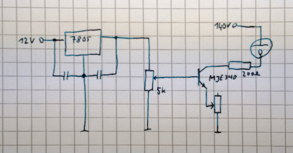
I’m using 12V input voltage here, because I also need 12V for the DC-to-DC converter’s input, and the final project should run off a single 12V power supply. There’s a 7805 which regulates the voltage to 5V, and a potentiometer which lets me adjust the current to the base of the transistor (by sweeping the voltage from 0 to 5V). There’s an additional potentiometer from the emitter of the transistor to ground, so I can play around with the exact resistor value – I figured out a value of 210Ω is fine. The third resistor here is just to protect the tube from over current should anything go wrong.
Here’s a video of the circuit in action:
In the pack of tubes I noticed some that would not light up all the way. The bar would get stuck at about 6cm, which is slightly more than half the length of the tube, at 12mA, and increasing the current further would make it brighter, but not longer any more. After some playing around I figured out they would need some kind of “burn-in”: This is where the second potentiometer in my circuit came in handy – I was able to increase the current further by lowering that resistor value. At about 25mA, the bar would start to grow longer again, reaching the top when the current was cranked up to almost 40mA. After this initial procedure, the tubes all respond nicely to a current of 0 to 12mA.
The next step in this project will be to build 16 of the transistor driver circuits, so I can drive all 16 of the tubes I have at the same time. Those will be controlled using PWM from a microcontroller. I have already tested applying the PWM directly to the base of the transistor without any additional low-pass filtering and it seems to work nicely. The microcontroller will take some numbers from a serial interface, and output the values on 16 PWM channels.