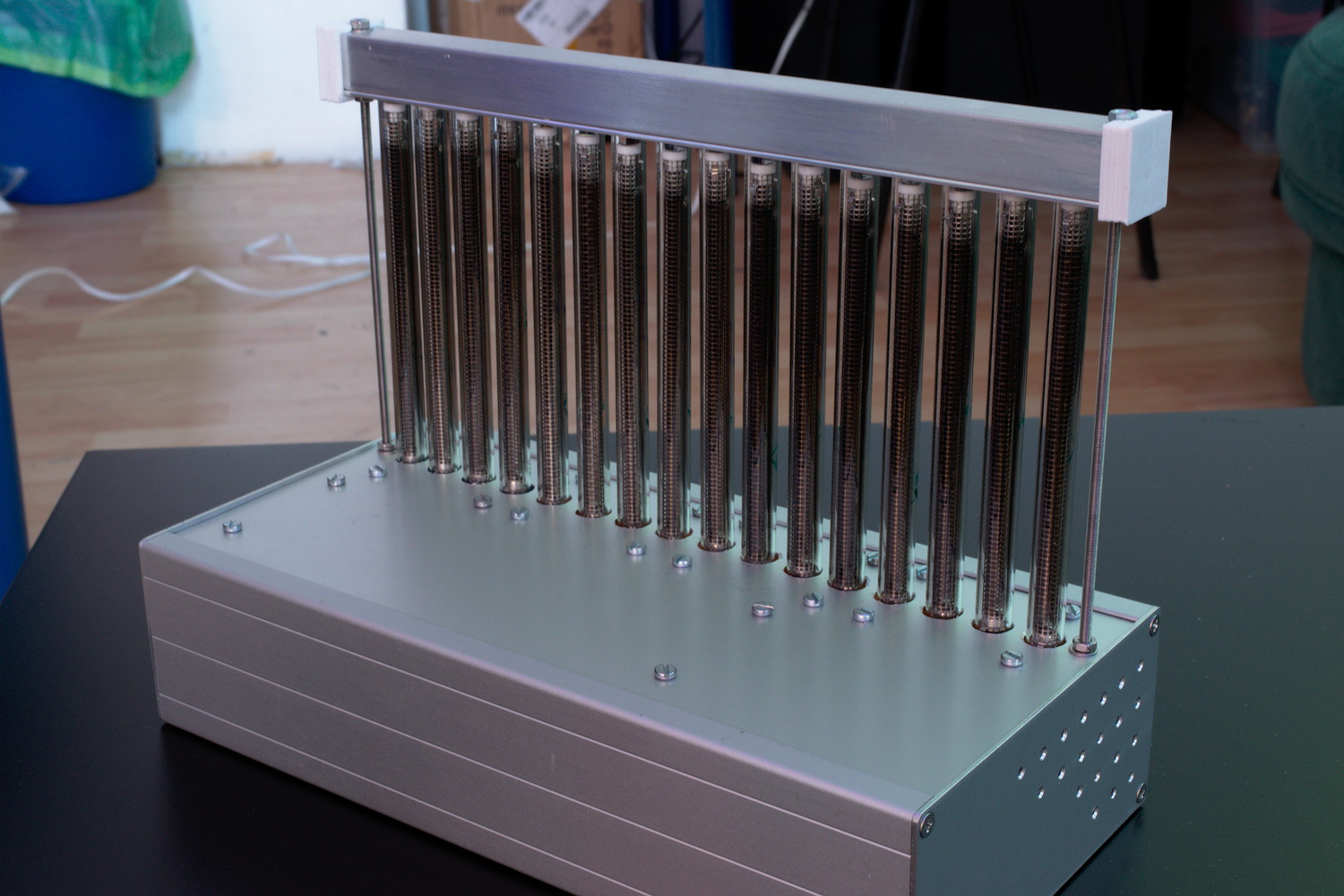
Finally the project is sort of finished. The 16 tubes are now mounted in a nice alumin(i)um case. The whole thing is powered by an external 12V power brick and gets its data through a USB port where it presents as a serial interface.
It took me a while and some searching on eBay, but I finally managed to find this nice case which fit the project perfectly. The fittings for the tubes were 3D-printed - each holder holds four tubes.
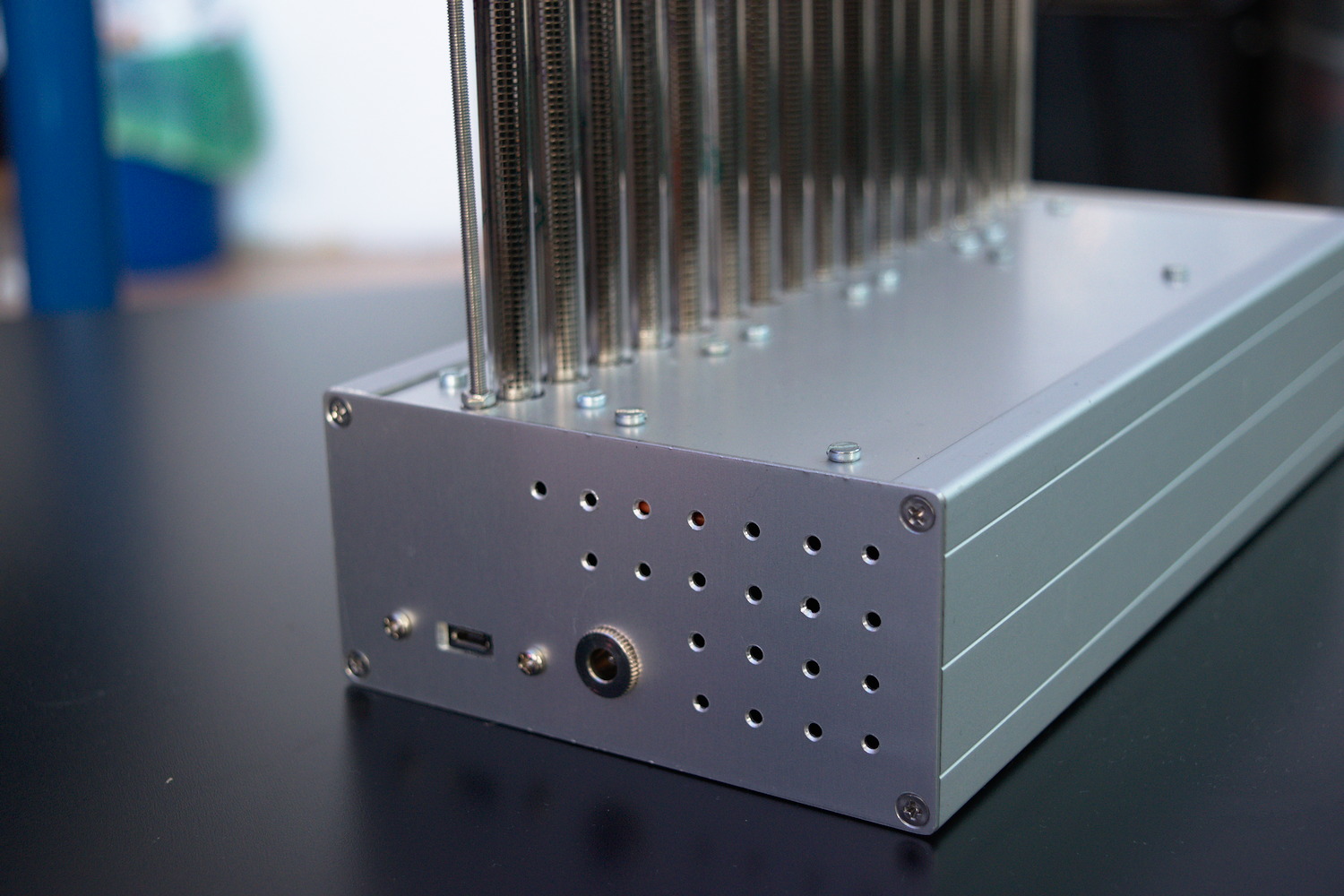
On the left hand side of the case, there are the connectors for the power supply and the USB, and because the whole thing runs quite hot (drawing up to 70W!), I decided to drill some ventilation holes in the sides of the case, too.
The bargraph nixies are kept upright by two pieces of aluminium L-section which form a tube that is fixed to the top of the unit by two lengths of threaded rod. A piece of plastic foam inside stops the tubes from rattling around when the device is moved.
Aside from the tube holders, there are some more 3D-printed parts on the case: the end caps for the top part, and the standoffs for the circuit bords.
The Electronics
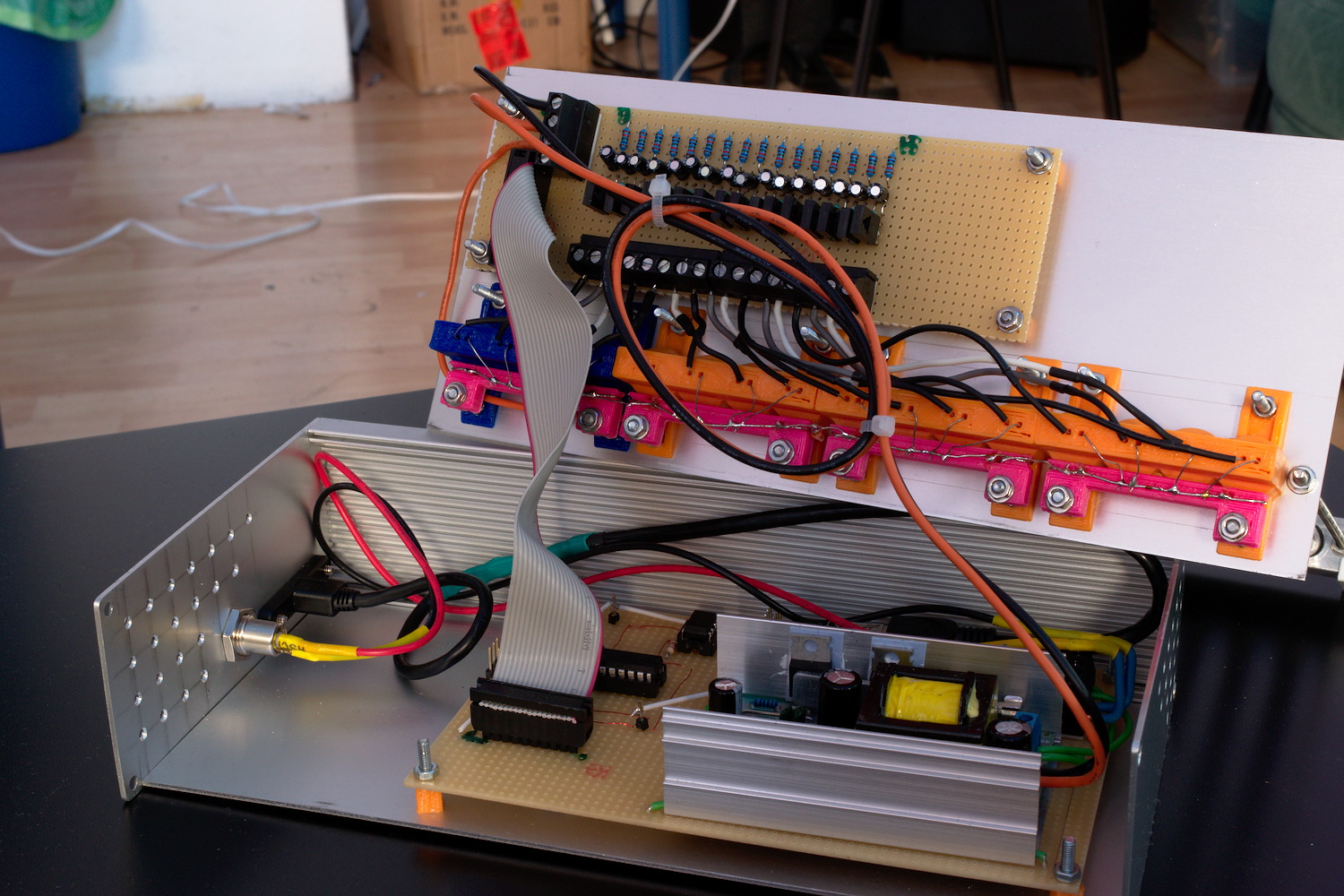
Main Board
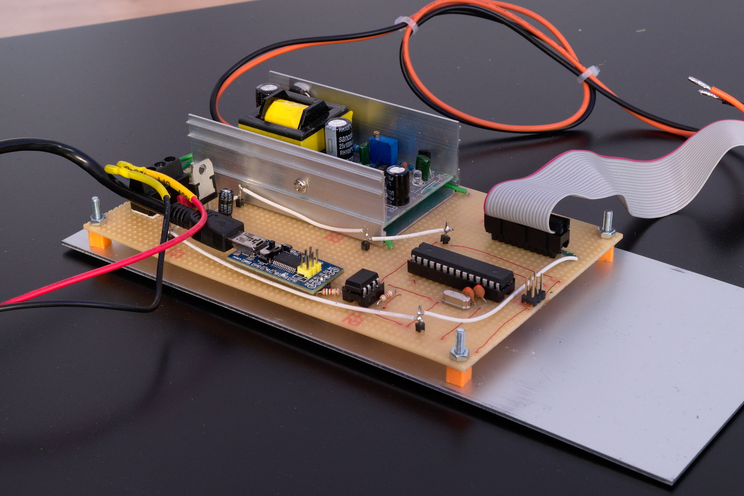
As mentioned in the previous article, the tubes need a fairly high DC voltage to get going. I’m using a 12-to-140V DC-DC converter I found on eBay. It came as a complete unit, which is fixed to the main board using some pieces of wire. Power to the whole device is provided using an external 12V/80W power brick.
Connectivity to the PC is provided by an FTDI serial interface board which is connected to the microcontroller using an opto-isolator, just in case - should anything go wrong with the high voltage part of the device, it’s less likely to leak through to my PC this way. There’s still a lot of room left on the main board, in case I decide to switch out the FTDI for something else later, maybe an ESP8266 or something similar?
The microcontroller is an ATMega 168A, and all it does is read a string of 16 numbers from the serial port and convert it to 16 PWM signals controlling the tube drivers.
The Driver Board
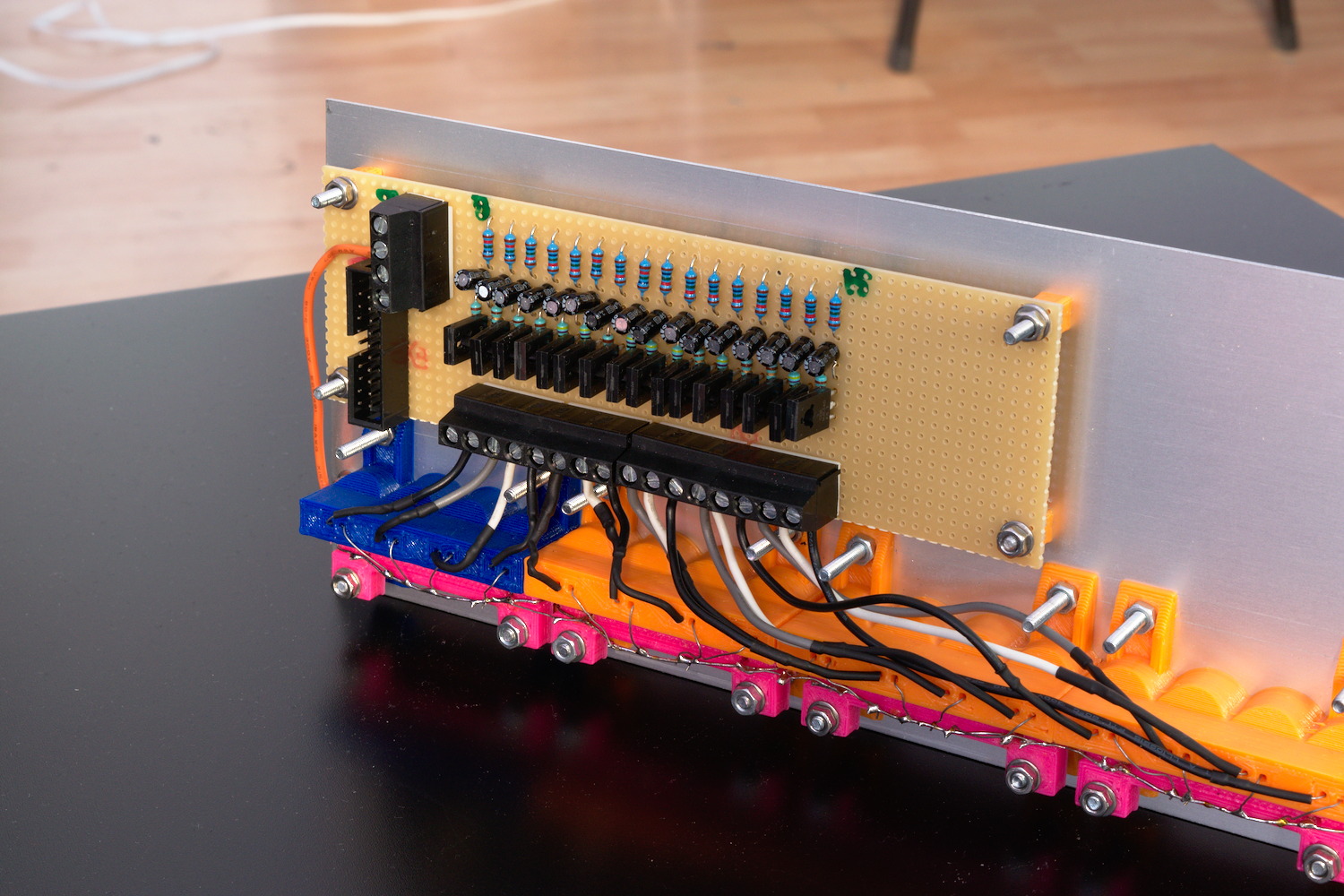
The driver board is connected to the main board using a piece of ribbon cable which carries the PWM signal for each tube, and two thicker wires for the connection to the power supply.
The controlling circuit for each tube is a modified version of the emitter follower current sink I showed in my previous post. I originally thought I could drive the transistor directly from a PWM signal, and the capacity of the tube would take care of the smoothing. This turned out not to be true, because the glowing band in the tube would be much longer and glow much dimmer than when the transistor was driven with a constant voltage. To compensate for that, I added an RC lowpass in front of each transistor’s base.
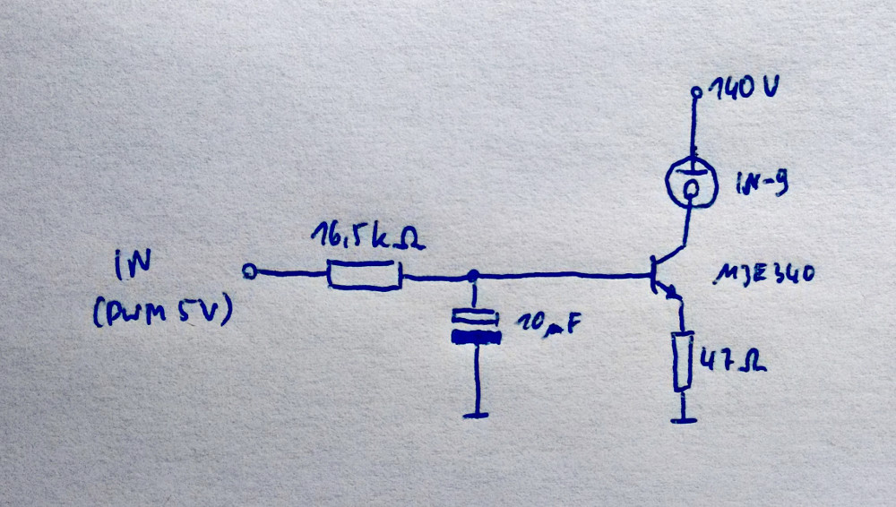
The circuit works like this: the tubes are current controlled, i.e. the more current there is flowing through it, the longer the glowing section gets. Therefore we want to control the current through the transistor and by extension through the tube.
Let’s have a look at the pictured circuit. If the input voltage is below the transistor’s forward voltage (about 0.6V), nothing happens. As soon as it rises above 0.6V, the transistor starts conducting, causing the voltage across the 47Ω resistor to rise until it is equal to the input voltage minus the forward voltage. As U = R · I, the current through the resistor is proportional to the voltage. The bulk of this current however does not come from the base of the transistor, but from its collector. In fact, the current through the base is negligible compared to the collector current. Therefore, we have an easy way of controlling the current through the indicator tube.
This circuit is replicated 16 times, once for each tube.
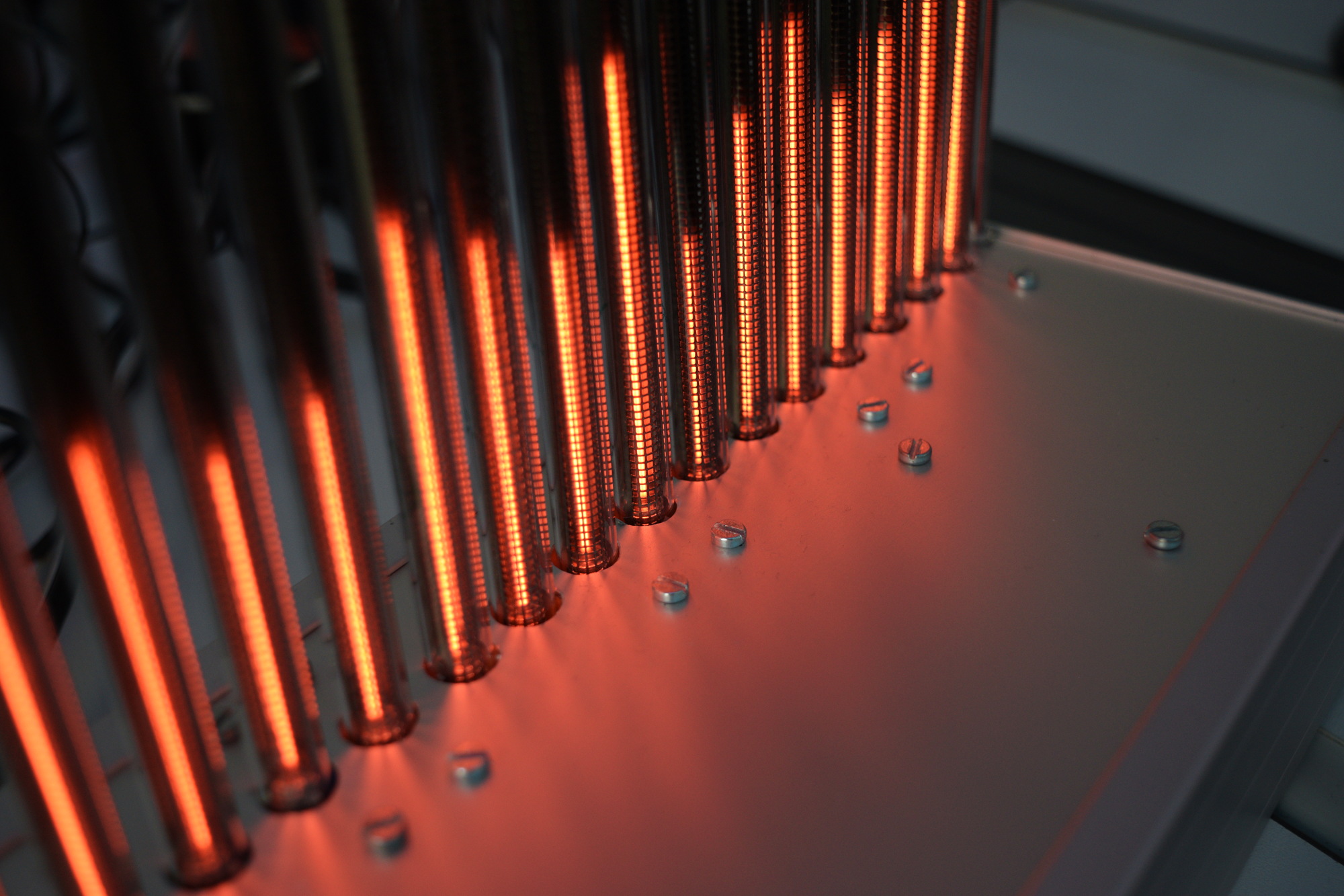
As I built the thing up, I noticed not all the tubes are the same. Some work nicely from the beginning, others take a slightly long warm-up phase during which it is not even possible to get the band to light over the whole length of the tube. After a while they settle down and work nicely, but even then they are not identical. Another issue I encountered was the fact that the band would sometimes appear in the middle instead of rising up from the bottom. This happens often when the current drops too quickly. Using bigger capacitors in the lowpass filters helped, as well as limiting the falloff speed in software. It also helps to not switch off the tubes completely, but keeping a tiny section at the bottom always on.
Originally, my plan was to display some kind of time series data scrolling sideways through the tubes (network traffic for instance), but this is not possible the way the device is now, because the same digital value will produce light bands of (slightly) varying lengths depending on which tube it is sent to. The scrolling effect just doesn’t look nice. Of course I could fine-tune the whole thing now, either in software or by adding a bunch of potentiometers, but the in its current state, it is at least fine for displaying animated patterns.
Here’s a little fire animation:
And here’s the obligatory spectrum analyzer:
Bonus Content
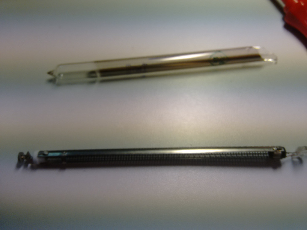
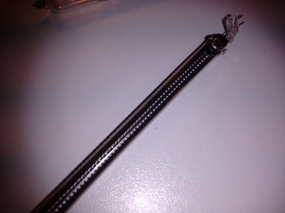
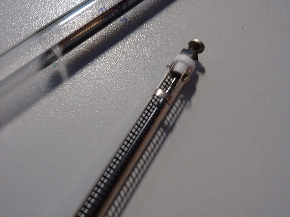
Of course something broke along the way! Well, in fact it happened when I displayed the thing at my local hacker space - the morning after a party, miraculously two of the tubes didn’t work any more. The glass was broken (I suspect some rough handling during asynchronous garbage collection), and now I can show you some pictures of a disassembled IN-9 bargraph nixie tube:
Thanks to LongHairedHacker for some hints regarding the electronics and φ for helping me take the photos.
I don’t have a fancy comment system yet, but if you wanna get in touch, just use Twitter and maybe reply my tweet about this.