Fixing a USB Stick
“Oh no! The only copy of my important stuff is on that USB stick, and it’s broken! What now?”
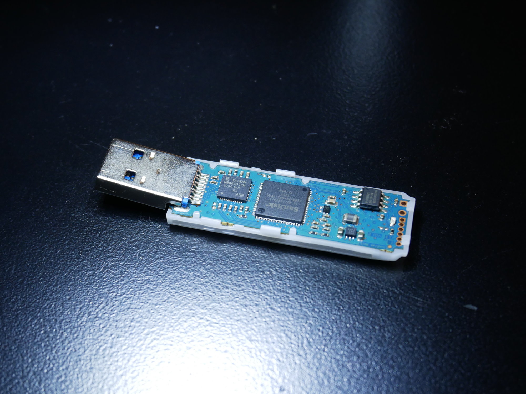
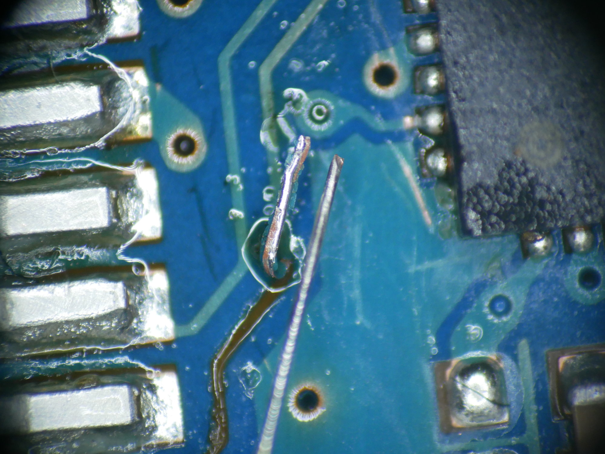
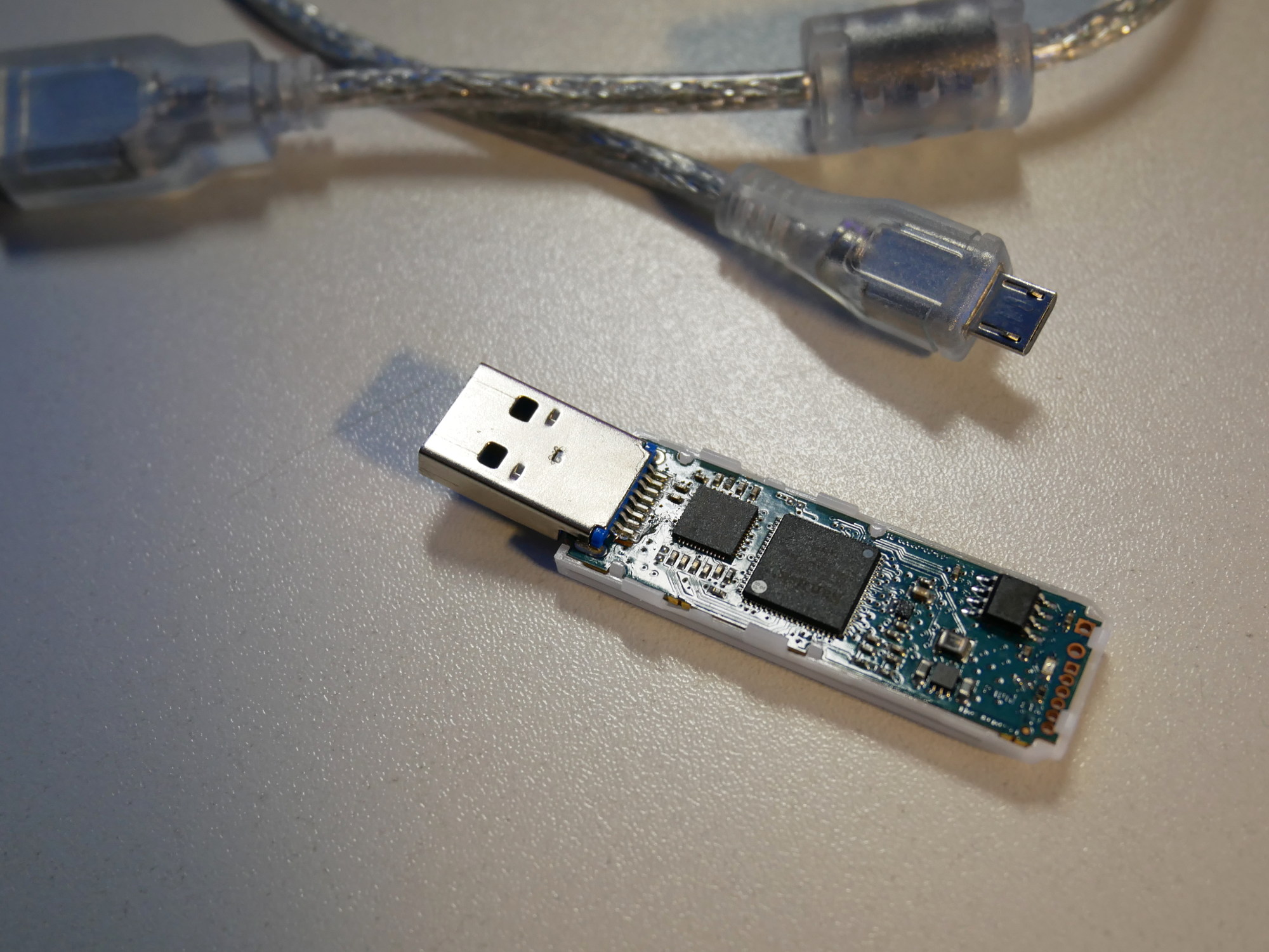
If you look at this photo closely, maybe you can already see the damage. On first glance, the pin has just come off the board, we can just solder it back on, no big deal, right?
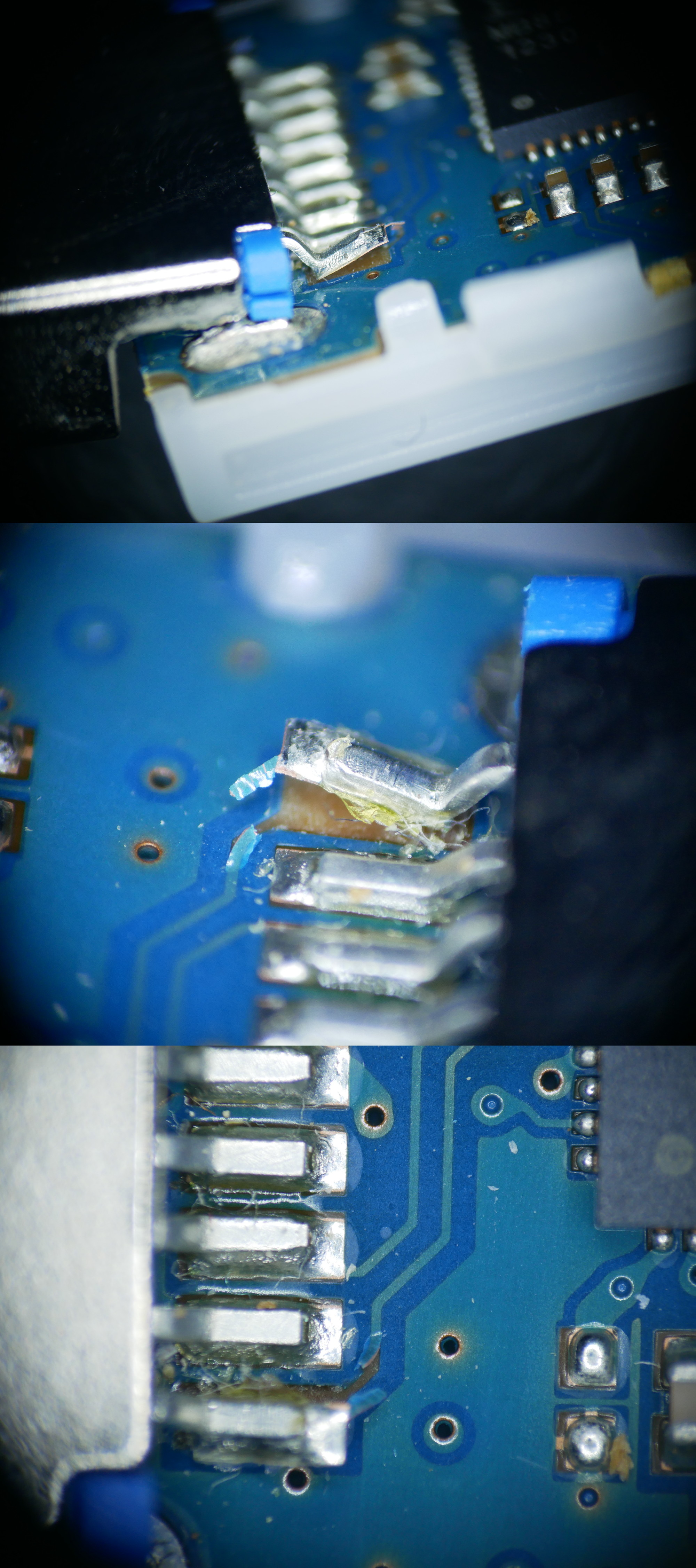
Nope - closer inspection under the microscope reveals that the whole pad has come off the board, including part of the trace leading to it.
So here, the fist things to do would
- don’t panic
- and don’t try to fix what’s not broken.
Obviously it is broken, but what pin of the USB connection is it, anyway?
A quick check with the continuity buzzer confirms it’s not one of the four “important ones”, i.e. those that are needed for USB 1.1 and 2.0 connections. This means the data are still accessible, just not over USB 3.0. Using a USB 2.0 extension lead I made sure the computer didn’t try to connect to it using USB 3, and dumped the data off of it.
Now, with the data safely backed up to the laptop, I could try and find out if I could actually fix the broken pin. Of couse it would only be a temporary fix - well, originally I had intended to patch the trace in order to be able to dump the data at all, so now after finding out I could dump the data without fixing the trace, it had become kind of pointless. But I still wanted to practice my soldering and just see if I could pull it off.

Soldering a wire to the pin of the chip on the other end of the trace would probably be a little small for what I can do, but using a pair of tweezers, I could pull off more of the damaged trace from the circuit board.
I scratched the underside of the trace clean with the tweezers, and with some extra flux added, I managed to tin it.
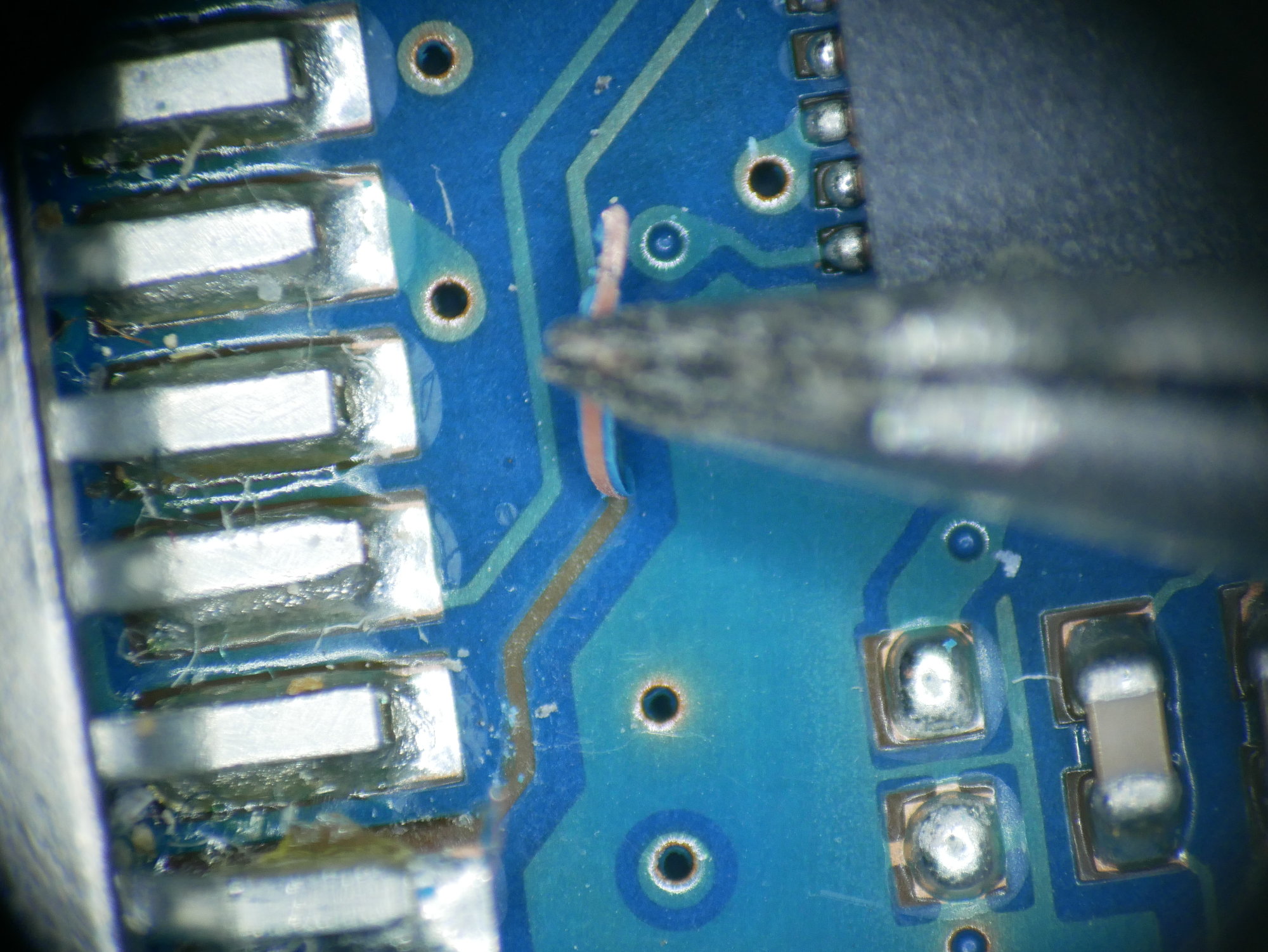
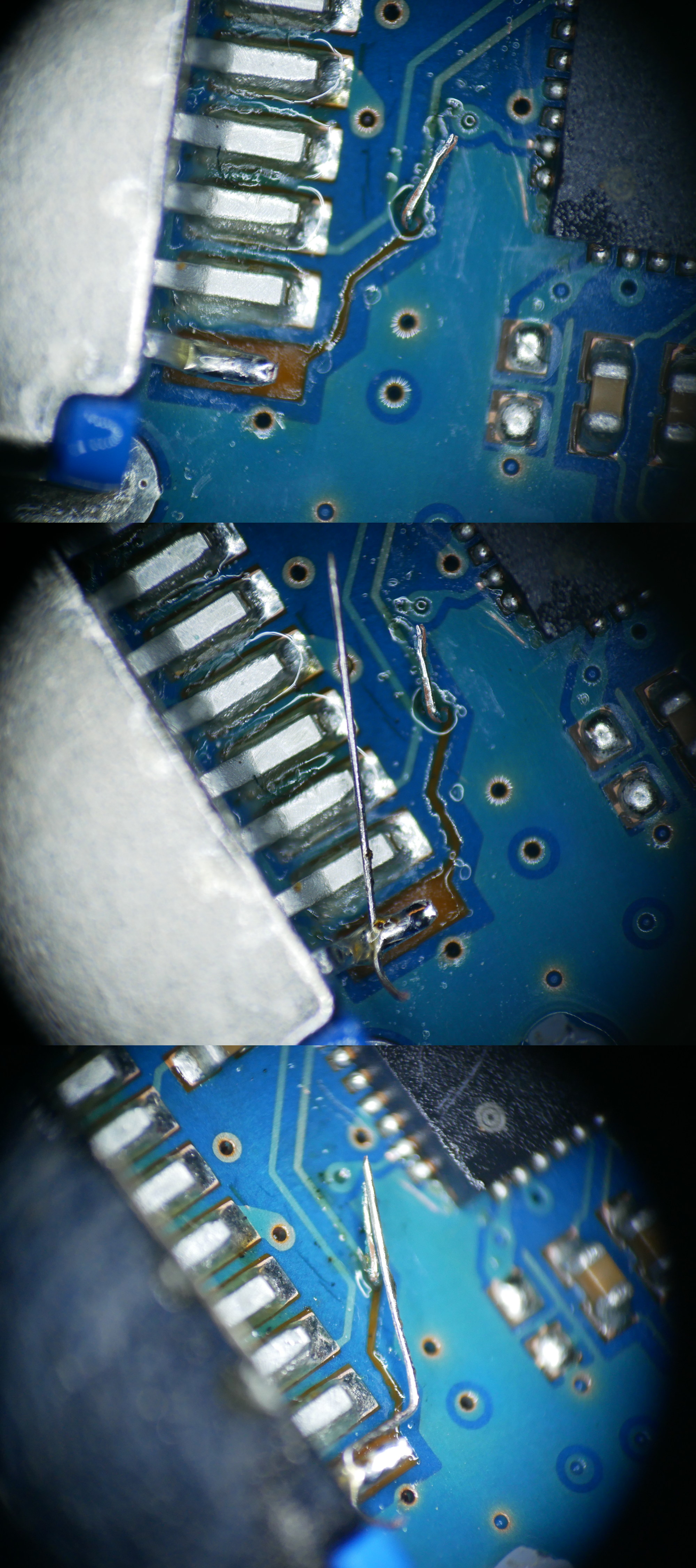
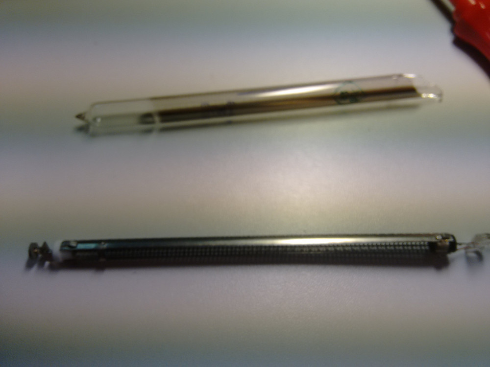
Next I needed something to patch the trace with. I found a piece of ribbon cable, from which I pulled out one single strand from one of the wires, and tinned it. Here it is for size comparison:
Using the soldering iron, I removed what was left of the pad and trace from the pin on the USB plug and tinned it with some fresh solder and soldered the wire onto it. Then I bent the wire into the right shape, so that it would just touch the lifted part of the trace.
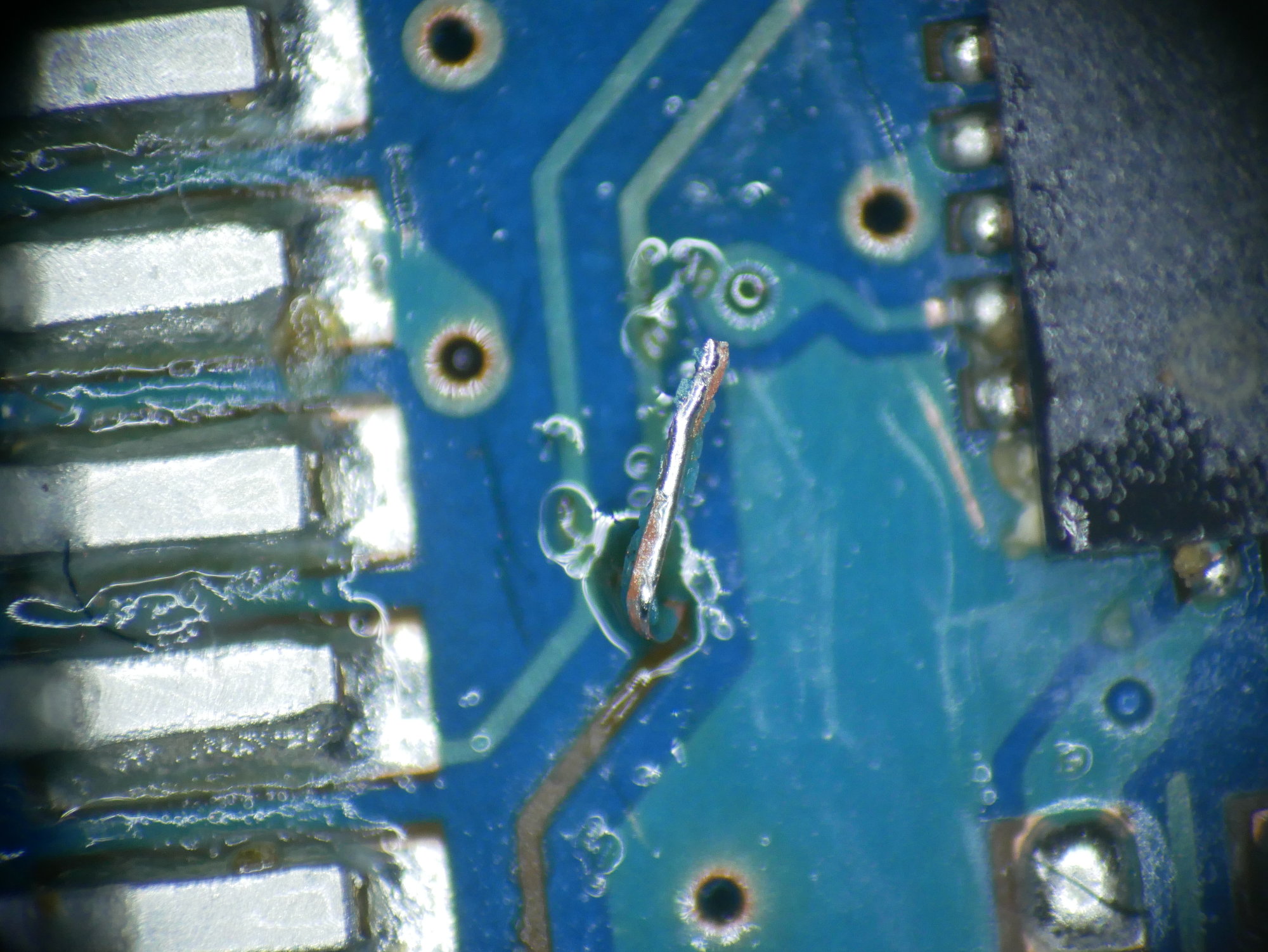
On to the final step: soldering the lifted trace and the wire together.
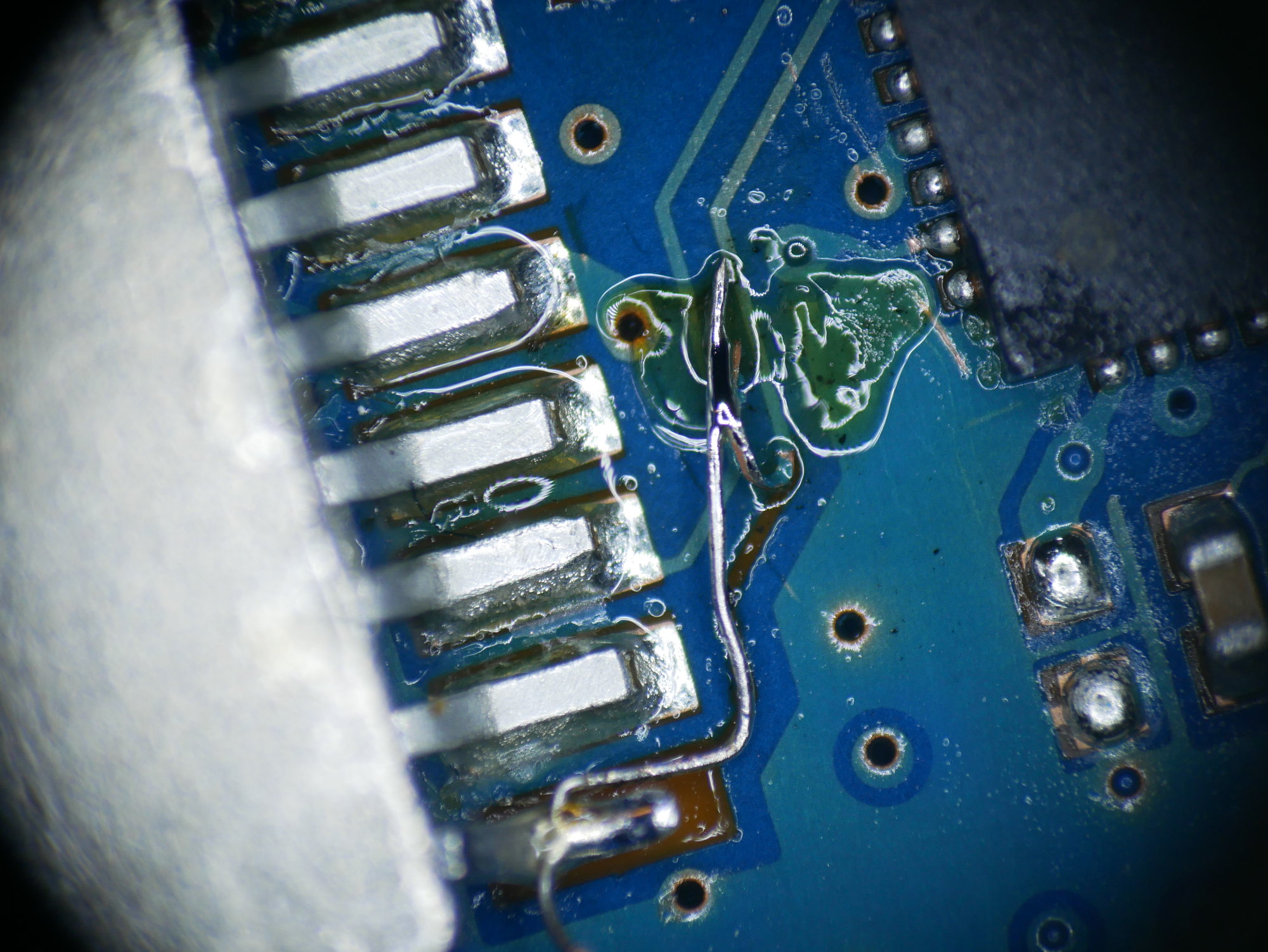
Here’s some more photos of it, after cleaning and from different angles.
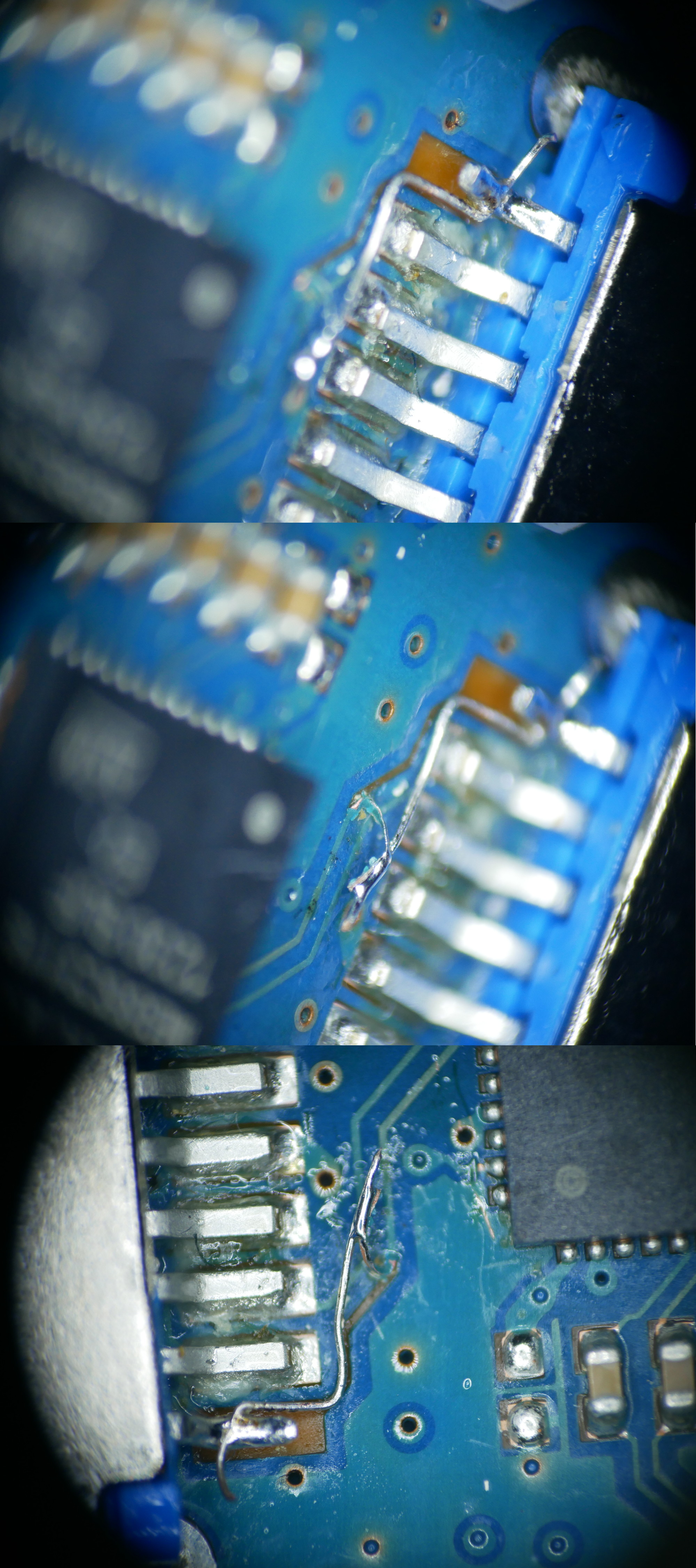
Here’s one more picture of the whole thing.
When plugged into the laptop now, it was discovered as a USB 3.0 device and read data at about 185MB/s - success!
IN-9 Bargraph Nixies – pt. 3

The Software
I was recently asked on Twitter how I managed to get 16 PWM channels out of an ATMega 168. This microcontroller only has 3 hardware PWM channels, so there’s a little trick involved using timer interrupts.
Here’s the timer setup routine, which is called at bootup:
void setup_timer() {
  TCCR0A |= (1 << WGM00) | (1 << WGM01);
  TCCR0B |= (1 << CS02) | (1 << WGM02);
  TIMSK0 |= (1 << TOIE0);
  OCR0A = 1;
}
Nothing magical so far: the three WGM bits are set, so that the timer is reset once the counter reaches the value in register OCRA, and then the timer overflow interrupt is fired. The CS bits are set so that the input of the timer is the main clock divided by 256. This frequency was chosen by experiment, timed so that the timer interrupt routine can comfortably execute and still allow for the main program to run in between timer interrupts. The timer overflow interrupt is enabled by setting TOIE0. Lastly, the output compare register OCR0A is preloaded with the value 1.
Here’s the next bit of code, the timer interrupt routine.
ISR(TIMER0_OVF_vect) {
  cli();
  pwm_bit();
  sei();
}

void pwm_bit() {
  static uint8_t index = 0;
  index = (index + 1) % 8;

  // Set timer value for the *next* bit (because OCR0A updates at BOTTOM)
  OCR0A = (0x01 << (index + 1) % 8) - 1;

  PORTB = bits_pb[index];
  PORTC = bits_pc[index];
  PORTD = bits_pd[index];
}
The interrupt handler itself just calls pwm_bit, and there the the interesting part happens. We’re using 8 bit PWM here, so we have an index that counts up from 0 to 7. First thing we do is update OCR0A for the next round. The formula calculates the new compare value so that the register cycles through the values 0, 1, 3, 7, 15, 31, 63, 127. This way, the timer interrupt does not fire at a constant rate, but at 1, 2, 4, … cycles (since the value 0 is also held in the timer counter register for one cycle).
Now we have the powers of two, i.e. the value of each individual bit, encoded in the length of time between timer interrupts - the least significant bit is worth one cycle, the next one two, and so on, until the last one which is worth 128 cycles. We just need to shift out the bits of each PWM channel to the corresponding output pins. The whole 16 channels do not fit on a single port of the AVR. In fact, because we also use the serial port of the ATMega, the 16 channels need to be spread out across three different ports. Another routine - we’ll have a look at it in a second - has already preloaded the PWM bits into three arrays of bytes.
Each array holds data for one port, laid out so that each byte contains the data to be emitted at a paricular time. For example, the byte in bits_pb[0] contains all the least significant bits of the PWM channels connected to PORTB. bits_pb[1] contains the next bits, and so on. bits_pb[7] consequently holds the most significant bits of the channels.
Of course, in this setup the PWM can switch multiple times per cycle. For example, here is what the output looks like for a value of 170, which conveniently is 10101010 in binary:
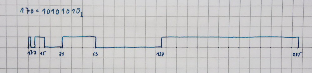
The signal stays low for 1 cycle (least significant bit is 0), then goes high for 2 cycles, low again for four cycles, high for 8 cycles, and so on. So it is not a clean PWM signal with a fixed frequency, but it gets the job done, because the capacitors connected to the outputs take care of the smoothing. But even without smoothing it is usable: I’m using the same scheme for 3 PWM channels in the lys project, where the outputs of the ATMega are connected to MOSFETs driving the LEDs.
Now the last bit of the code is where the input is transformed to the bit patterns for the PWM. The input is an array of numbers in the range [0 .. 255]. Here’s the code that transforms it into the bit patterns for the ports:
void pwm_set(const uint8_t* val) {
  for (uint8_t bit_index = 0; bit_index < 8; bit_index++) {
    uint8_t mask = 1 << bit_index;

    // Values 0..5 to PORTC[0..5].
    for (uint8_t val_index = 0; val_index < 6; val_index++) {
      if (val[val_index] & mask)
        bits_pc[bit_index] |= (1 << val_index);
      else
        bits_pc[bit_index] &= ~(1 << val_index);
    }

    // Values 6..8 to PORTB[0..2].
    for (uint8_t val_index = 0; val_index < 3; val_index++) {
      if (val[val_index + 6] & mask)
        bits_pb[bit_index] |= (1 << val_index);
      else
        bits_pb[bit_index] &= ~(1 << val_index);
    }

    // Values 10..15 to PORTD[1..7].
    for (uint8_t val_index = 1; val_index < 8; val_index++) {
      if (val[val_index + 8] & mask)
        bits_pd[bit_index] |= (1 << val_index);
      else
        bits_pd[bit_index] &= ~(1 << val_index);
    }
  }
}
The outer for-loop shifts the 1 in the mask byte through all 8 bit positions. Then for each output port there is a for-loop, which iterates over the PWM channels connected to that particular port. If the masked bit in the input (val[val_index] & mask) is set, a 1 is written on the bit position of that channel (bits_p…[bit_index] |= (1 << val_index)), otherwise, a 0 is written there. Since several of the ATMegas pins are fixed for some of the internal functions (the serial port for example), we have to to make do with the ones that are still available as outputs, hence the seemingly random layout of output pins used: pins C0 to C5, B0 to B2, and D1 to D7.
And there we go, 16 channel PWM on an ATMega 168.
IN-9 Bargraph Nixies – pt. 2
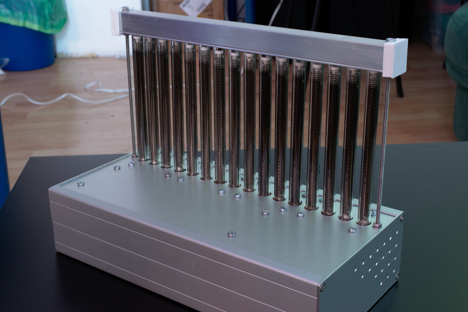
Finally the project is sort of finished. The 16 tubes are now mounted in a nice alumin(i)um case. The whole thing is powered by an external 12V power brick and gets its data through a USB port where it presents as a serial interface.
It took me a while and some searching on eBay, but I finally managed to find this nice case which fit the project perfectly. The fittings for the tubes were 3D-printed - each holder holds four tubes.
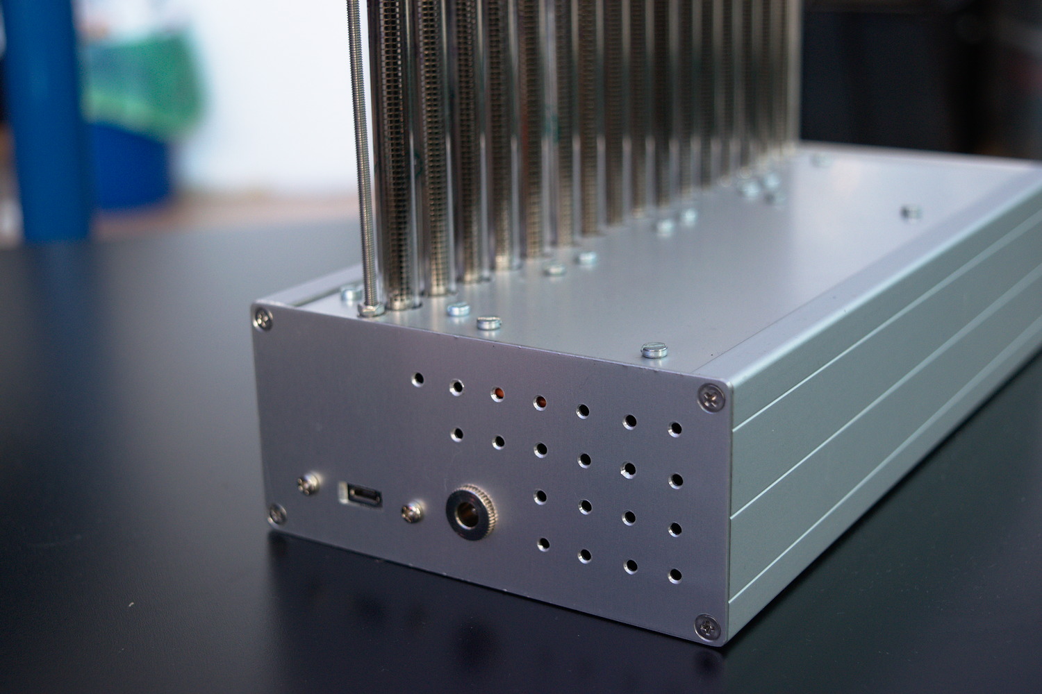
On the left hand side of the case, there are the connectors for the power supply and the USB, and because the whole thing runs quite hot (drawing up to 70W!), I decided to drill some ventilation holes in the sides of the case, too.
The bargraph nixies are kept upright by two pieces of aluminium L-section which form a tube that is fixed to the top of the unit by two lengths of threaded rod. A piece of plastic foam inside stops the tubes from rattling around when the device is moved.
Aside from the tube holders, there are some more 3D-printed parts on the case: the end caps for the top part, and the standoffs for the circuit bords.
The Electronics
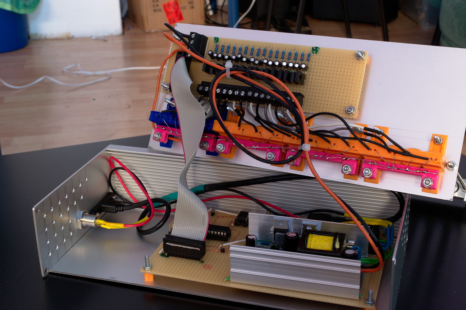
Main Board
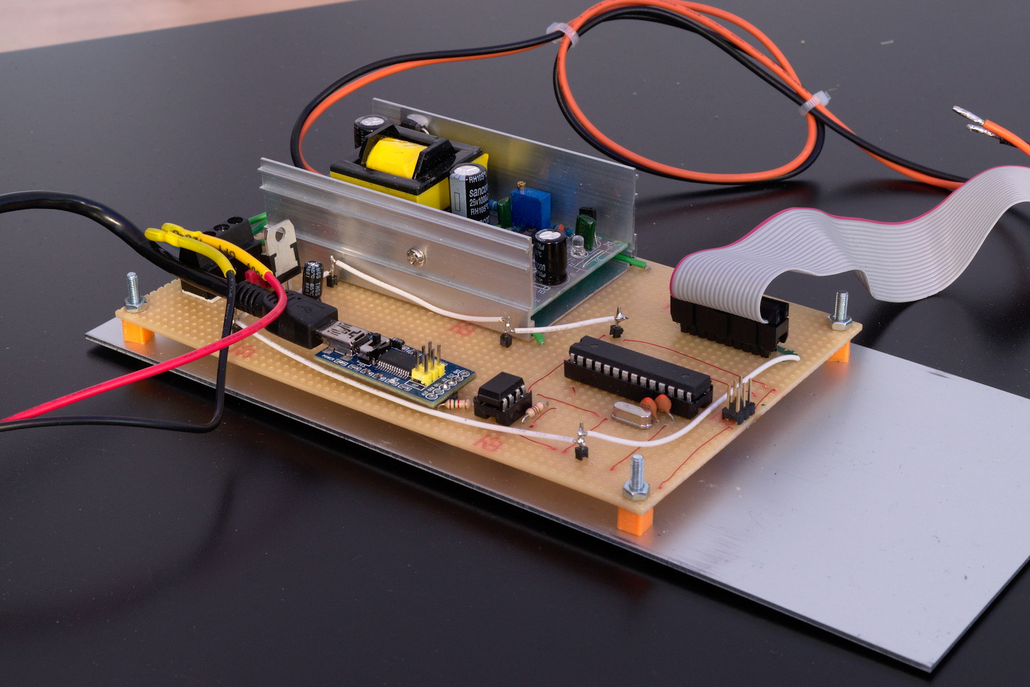
As mentioned in the previous article, the tubes need a fairly high DC voltage to get going. I’m using a 12-to-140V DC-DC converter I found on eBay. It came as a complete unit, which is fixed to the main board using some pieces of wire. Power to the whole device is provided using an external 12V/80W power brick.
Connectivity to the PC is provided by an FTDI serial interface board which is connected to the microcontroller using an opto-isolator, just in case - should anything go wrong with the high voltage part of the device, it’s less likely to leak through to my PC this way. There’s still a lot of room left on the main board, in case I decide to switch out the FTDI for something else later, maybe an ESP8266 or something similar?
The microcontroller is an ATMega 168A, and all it does is read a string of 16 numbers from the serial port and convert it to 16 PWM signals controlling the tube drivers.
The Driver Board
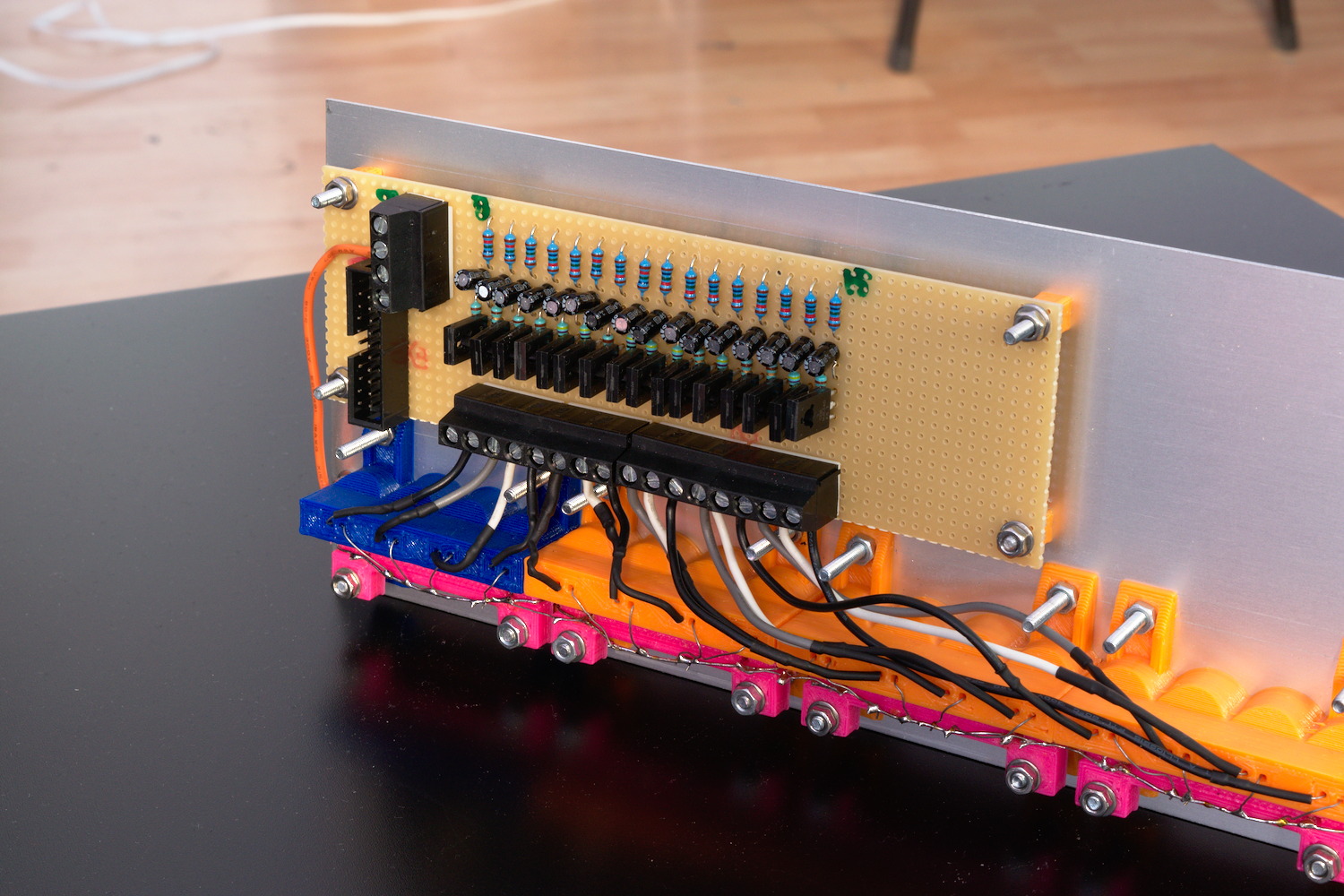
The driver board is connected to the main board using a piece of ribbon cable which carries the PWM signal for each tube, and two thicker wires for the connection to the power supply.
The controlling circuit for each tube is a modified version of the emitter follower current sink I showed in my previous post. I originally thought I could drive the transistor directly from a PWM signal, and the capacity of the tube would take care of the smoothing. This turned out not to be true, because the glowing band in the tube would be much longer and glow much dimmer than when the transistor was driven with a constant voltage. To compensate for that, I added an RC lowpass in front of each transistor’s base.
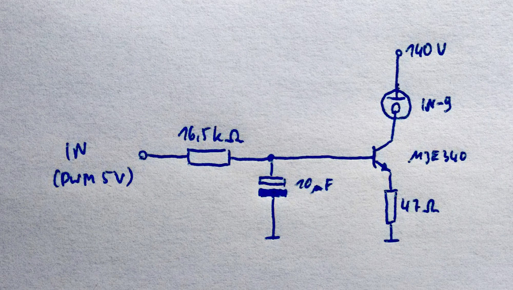
The circuit works like this: the tubes are current controlled, i.e. the more current there is flowing through it, the longer the glowing section gets. Therefore we want to control the current through the transistor and by extension through the tube.
Let’s have a look at the pictured circuit. If the input voltage is below the transistor’s forward voltage (about 0.6V), nothing happens. As soon as it rises above 0.6V, the transistor starts conducting, causing the voltage across the 47Ω resistor to rise until it is equal to the input voltage minus the forward voltage. As U = R · I, the current through the resistor is proportional to the voltage. The bulk of this current however does not come from the base of the transistor, but from its collector. In fact, the current through the base is negligible compared to the collector current. Therefore, we have an easy way of controlling the current through the indicator tube.
This circuit is replicated 16 times, once for each tube.
As I built the thing up, I noticed not all the tubes are the same. Some work nicely from the beginning, others take a slightly long warm-up phase during which it is not even possible to get the band to light over the whole length of the tube. After a while they settle down and work nicely, but even then they are not identical. Another issue I encountered was the fact that the band would sometimes appear in the middle instead of rising up from the bottom. This happens often when the current drops too quickly. Using bigger capacitors in the lowpass filters helped, as well as limiting the falloff speed in software. It also helps to not switch off the tubes completely, but keeping a tiny section at the bottom always on.
Originally, my plan was to display some kind of time series data scrolling sideways through the tubes (network traffic for instance), but this is not possible the way the device is now, because the same digital value will produce light bands of (slightly) varying lengths depending on which tube it is sent to. The scrolling effect just doesn’t look nice. Of course I could fine-tune the whole thing now, either in software or by adding a bunch of potentiometers, but the in its current state, it is at least fine for displaying animated patterns.
Here’s a little fire animation:
And here’s the obligatory spectrum analyzer:
Bonus Content
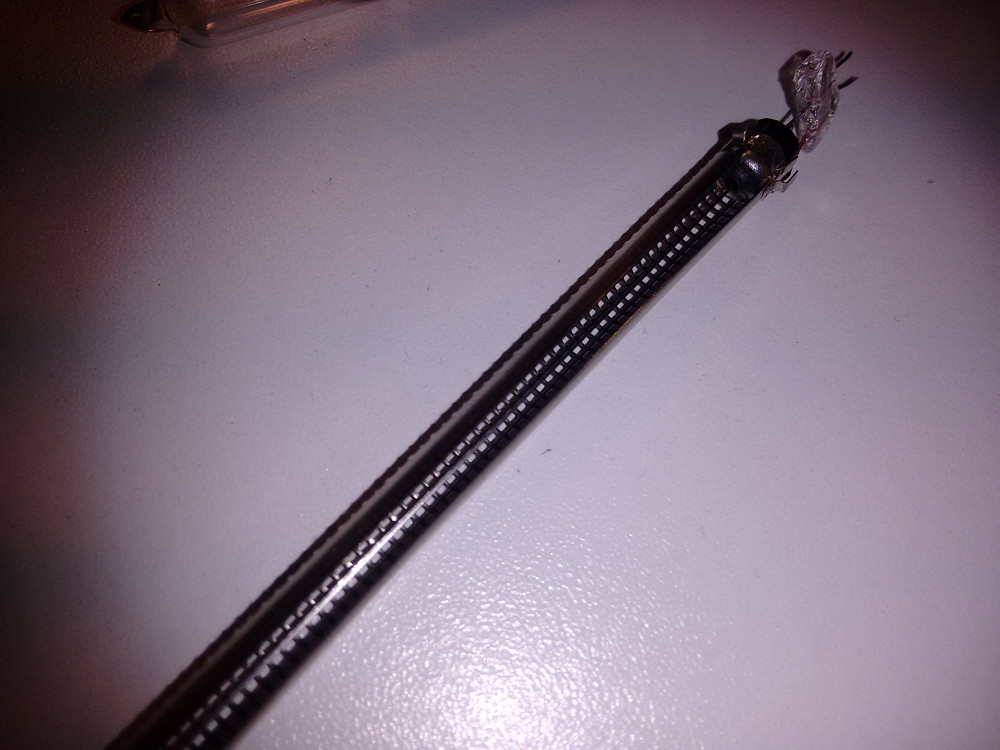
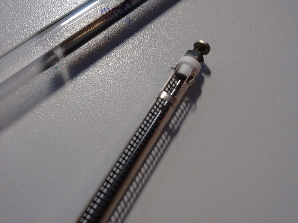
Of course something broke along the way! Well, in fact it happened when I displayed the thing at my local hacker space - the morning after a party, miraculously two of the tubes didn’t work any more. The glass was broken (I suspect some rough handling during asynchronous garbage collection), and now I can show you some pictures of a disassembled IN-9 bargraph nixie tube:
Thanks to LongHairedHacker for some hints regarding the electronics and φ for helping me take the photos.
I don’t have a fancy comment system yet, but if you wanna get in touch, just use Twitter and maybe reply my tweet about this.
IN-9 Bargraph Nixies – pt. 1
Recently I got some Russian ИН-9 / IN-9 “Bargraph Nixie” tubes from eBay. Although I haven’t yet found out what those devices were used for originally, there’s a lot of videos on YouTube where you can see fun things people do with them.

The tubes run off about 140V DC, and the length of the bar is controlled by the current through the tube. It’s zero to about 12mA to sweep the bar across the length of the tube.
I looked into ways to drive them, and found this document: http://www.die-wuestens.de/rd/IN9-2.pdf
To get the required voltage, I use a 140V DC-to-DC converter, which should be powerful enough to drive several of the tubes at the same time. Using the rather simplistic “Current Sink IN-9 Driver” from the PDF as a reference, I did a preliminary test on all of the tubes.
As described in the document, the graph grows longer as you increase the current, and reaches the top of the tube at about 12mA. Increasing the current further will make the bar glow a bit brighter. Here’s the circuit I’m using for now:
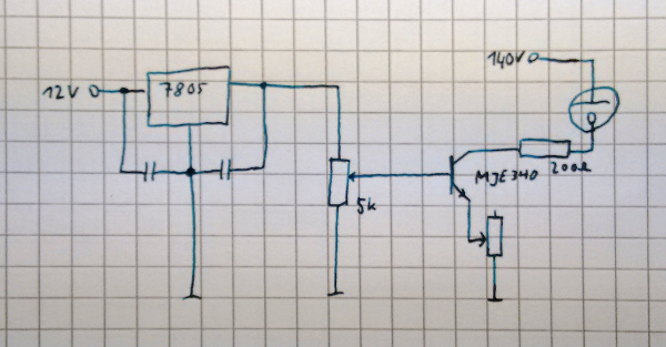
I’m using 12V input voltage here, because I also need 12V for the DC-to-DC converter’s input, and the final project should run off a single 12V power supply. There’s a 7805 which regulates the voltage to 5V, and a potentiometer which lets me adjust the current to the base of the transistor (by sweeping the voltage from 0 to 5V). There’s an additional potentiometer from the emitter of the transistor to ground, so I can play around with the exact resistor value – I figured out a value of 210Ω is fine. The third resistor here is just to protect the tube from over current should anything go wrong.
Here’s a video of the circuit in action:
In the pack of tubes I noticed some that would not light up all the way. The bar would get stuck at about 6cm, which is slightly more than half the length of the tube, at 12mA, and increasing the current further would make it brighter, but not longer any more. After some playing around I figured out they would need some kind of “burn-in”: This is where the second potentiometer in my circuit came in handy – I was able to increase the current further by lowering that resistor value. At about 25mA, the bar would start to grow longer again, reaching the top when the current was cranked up to almost 40mA. After this initial procedure, the tubes all respond nicely to a current of 0 to 12mA.
The next step in this project will be to build 16 of the transistor driver circuits, so I can drive all 16 of the tubes I have at the same time. Those will be controlled using PWM from a microcontroller. I have already tested applying the PWM directly to the base of the transistor without any additional low-pass filtering and it seems to work nicely. The microcontroller will take some numbers from a serial interface, and output the values on 16 PWM channels.
i3 on a Laptop: Quickly Switch Monitors – Revisited
You remember that cool hack about switching monitor using i3nagbar I posted a few months ago? If you don’t, it’s about two posts down from here.
Meanwhile I’ve come up with something even better. I wanted to have a look at Python and Gtk, so I re-implemented the hack with a nicer GUI and more features.
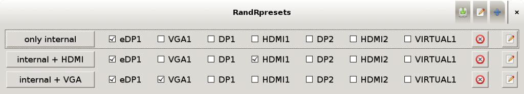
 So here is randrpresets! It’s on my github for you to use and fork. The idea is as follows: Bind it to a hotkey – if you want to plug in an extra monitor, hit that hotkey once, the dialog pops up and you just click the screen setup you like (say, laptop screen plus projector on VGA). That’s all.
The little tool allows you to add new presets with a click and customize them with a few more clicks. It also allows you to specify a post-command which is executed after a new preset is applied, e.g. for re-fitting your nice wallpaper or getting that lazy docking station keyboard to work. You can save your presets to a config file, and since everything can be edited with a few clicks, you won’t ever have to open that file in a text editor (but you can, it’s just JSON).
Other than that, randrpresets pretty much tries to get out of your way. It closes the instant a new preset is applied, and there’s none of that rotation and screen flipping stuff you never need. I’m planning to distinguish between right-of and left-of though (at the moment all the outputs are just a long chain of right-of entries).
Test driving Sublime Text
Introduction
I think a text editor is the most important and most versatile tool an advanced computer user has. I also think you should not have different text editors for different tasks—i.e., an IDE for C++, a different one for Java, an editor specifically tailored for editing TeX files, and so on. In my oppinion, everyone should have an “allround” text editor, if only for the stuff you don’t want to open your IDE for.
Ever since Kile broke down on me in the middle of writing my bachelor’s thesis, I’ve been using vim exclusively. Over the years I learned lots of commands and tricks, customized it with plugins, modified plugins and made some useful additions on my own. I was very happy with it, and we were getting along nicely, me and vim.
Recently, Sublime Text started to gain a lot of popularity among my friends. I had read about it, but brushed it off quickly. It wasn’t going to be as cool or powerful as vim, and even if it were, why should I relearn all those commands. I was envious of the minimap, so I made one for vim, and found out that it looks nice, but is not useful to me (I know some who use it a lot in Sublime, but I din’t. I kept it on at all times when I tried sublime, but never found it really helpful).
A while later I saw more and more people around me use Sublime Text, most of them former vim users. So I talked to them, and found out some of them just never knew enough vim to be comfortable, but others have been power-using vim for years, and just like Sublime better now.
I finally decided to give it a shot. I’ve been using the evaluation version for about a month now, while making a list of things that I like better on Sublime, and things that I miss from vim.
GUI Beauty
The first thing I noticed: Sublime is fast, and it looks good.
Let’s face it—vim sometimes just feels old. The fact that gvim is little more than a fancy text terminal running vim doesn’t help, and probably makes it slower than it should be. It also makes some stuff (near-)impossible: A minimap, or good looking indent guides for instance. Sublime draws fine dotted lines that can be hidden when the cursor’s outside of the indented area. This makes it easy for me to see what’s between your { and }. In vim, you can set listchars so you can see the indent tabs, but you can’t do anything like that using spaces.
There also is a plugin which highlights your indentation using different background colors. Both ways cause so much visual clutter on my screen that I can’t concentrate on the actual contents of the file. It’s the same with the ruler marking the 80th (or whatever number you like) column. In vim you just have a different highlight for that column, which most of the time defaults to a big red bar. You can set it to produce “awkward underscores” or just the letter in that position turning red (which doesn’t help if it’s whitespace). But not the fine dotted line Sublime can display there.
What’s especially nice about Sublime is the persistence of vision while scrolling. When jumping to another part of the file, the screen does not instantly refresh, but instead visibly (and fluently) scrolls there. This and the well-visible minimap marker is very practical to me (guess that’s the one useful thing about the minimap—it’s a really wide scrollbar. I know roughly how far I jumped and where I ended up, which helps me to find my way around a file. In vim, there are only line numbers, a percent display and, if activated, relatively narrow scrollbars, all of which update instantly and thus only give you a feel for how far you jumped if you conciously pay attention to them. Semi-relatedly, for some reason I don’t understand, I happen to accidentally push PgDn every once in a while. On vim, pressing PgUp afterwards takes me back somewhere into the general vicinity of where I came from, while on Sublime, PgUp takes me back to the exact spot I came from, which is much less destructive to my train of thought.
A fun thing about Sublime you might not have noticed: The thumb-buttons on the mouse (forward / back) allow you to cycle through the open tabs. Before I tried Sublime I tried to implement the same behaviour in vim, but faild. Now I know that it’s not as practical as I thought.
Quick Navigation
I had to re-learn some things. I knew full well there was a “vintage mode” which provided a limited amount of vim commands in sublime, but I decided to leave that deactiavated at first, so I can see and learn how Sublime works without constantly thinking “that doesn’t work the way it’s supposed to” (i.e. “that doesn’t work the same way as in vim”).
What struck me most is that there’s no hotkey for “Save all”—there’s not even a :wa in vintage mode. I often edit multiple files, and after I make some changes, I go :wa and head to the terminal where I run the build process. It took me a while to realize I could use the menu mnemonics in the same way as the :-commands in vim. And “Alt-f l” is even shorter than “:wq”, even if you forget that you have to use a shift key for the :, too.
If you don’t like menu mnemos, there’s the Ctrl-Shift-p command palette which gives you quick access to a lot of commands. While it’s not as powerful as vim’s command line, it’s certainly easier to use, because it tells you what it can do instantly, and you just have to vaguely remember or guess the name of the thing you’re trying to do.
What’s really cool is the Ctrl-p “open anything” function, which basically allows you to quickly open any file in your source tree. I use it a lot, and I really like it. Like the command palette, it searches with just enough fuzziness to be compatible with my style of typos. I wonder whether there’s something similar for vim.
Window Management
Seeing that list, Sublime has a lot going for it, but I still miss vim for several reasons:
The handling of buffers, tabs, windows and splits in vim suits my style much better than the layouts of Sublime: In Sublime, I can only choose between several “layouts”, there is no way to just “:split” something. If I want two views of the same file, I have to open the file twice. Which adds all the fun associated with saving to that file from multiple tabs. The hierarchy of “groups (i.e. splits) contain tabs” is also not suitable to my style. When I write C++ code in vim, I usually have one tab for each pair of .cpp and .h file, which is :vsplit, one split contains the .cpp and the other contains the .h file. This is not possible in Sublime, though I quickly got used to just pressing Alt-o to toggle between header and implementation. Sublime’s handling of splits and tabs feels to stiff for me. I often split the window containing the .h file further, to allow me to view a different .h file which contains stuff relevant to what I’m doing at the moment. In vim, this only requires a few keystrokes, but in Sublime it’s not easily possible. I realize that I don’t really need it in Sublime: I don’t have a split with the .h file constantly open, so I can just press Ctrl-Alt-2 to split the window and drag the relevant tab into the newly generated region (probably there’s also keyboard shortcuts that do this).
Still, vim is much more flexible when it comes to this, and I like this flexibility. Sublime has no notion of “an empty tab you can fill with buffers”—it works the other way around, having “an empty region you fill with tabs”. I can’t get used to that, maybe because tabs for me feel like different contexts I can switch between, much like some people use virtual desktops.
Files and Contents
A small thing that disturbs me a lot is the notion Sublime has of a “changed file”. When I open a file and change something, both Sublime and vim notice that and mark the file a changed, giving the Tab a little plus or dot. When I undo that change again, vim notices and removes the plus. Sublime only removes the little dot when I explicitly use the “Undo” command. Typing a character and deleting it using Backspace or Del still keeps the file as “changed” in Sublime’s way of handling things.
I don’t like my files to contain trailing spaces, or lines that just contain a few spaces and nothing else. Vim can highlight trailing spaces, making it easy to avoid or remove them. Sublime has a plugin which should do the same, but this never worked the way I like it, and stopped working altogether after a week or so. There’s a “remove trailing spaces when saving a file” feature that might be a solution to this problem, but I feel it might bite me in the rear end one day, so I avoid it. I also noticed the auto-indentation of Sublime is much more prone to insert lines only containing spaces than vim’s auto-indentation.
Indentation
Which brings us to the next point: Indentation. I like the way vim’s auto-indentation works, and I can’t even say why. Maybe I’m just so used to it, but I’d say, it just works. Can’t say the same thing about Sublime though: Just indenting while I’m typing works fine, but auto-indenting a block of text is a mess: I couldn’t figure out what I was doing wrong, but I never got reindent (which is conveniently bound to the = key in vintage mode, along with == and %=) to really work. There was the rare case where it worked, but most of the time everything but the first three lines got indented a level too far, or not correctly indented at all.
Sublime has an autodetection mechanism for whether your file is indented using tabs or spaces, which is used for the auto-indenter from then on. I sometimes edit files on which multiple people with different editor settings have worked on in the past, and the files therefore have parts indented with tabs, and other parts indented with spaces. On those files, the autodetection naturally fails, and using reindent or Ctrl-] (the equivalent to » in vim) results in badly mixed indentation, containing tabs and spaces on the same line sometimes. And since reindent does not just convert one to the other, but tries to keep as much of the mess as possible, it’s not easily fixed either. Luckily there is a “Convert indentation to Spaces” option in the menu.
Multicursors
When someone shows off how cool Sublime is, they will most likely first bring up the minimap, and then the multicursors. Both features look cool, and at first I thought, “wow! That’s the FUTURE! I absolutely need those multicursors!”—I even tried to find and/or make a vim plugin that gives me multicursors (spoilers: Couldn’t make it work right).
Well, in Sublime I worked with them for a while, and yes, they are practical. But when I took a step back I soon noticed that I can do alsmost everything I use them for just as quickly and effortlessly in vim: Vim has macros, visual block mode, even the . key is enough most of the time (plus little things like ciw or viwp). And if those are not enough, just use a regex. Vim lacks the instant visual feedback, and the capability to do all the changes at the same time. But that doesn’t mean it’s slower or more complicated to do them. It just doesn’t look as cool.
I’m not saying Sublime can’t do it “the vim way”—I’m just saying that I feel somehow encouraged to use the multicursors when I probably shouldnt, because a regex or macro would have been quicker. Sometimes they are useful, but I can do without them. Maybe someone makes a vim plugin that works one day.
Smooth Visuals
About looking cool: Sublime’s cursor blinks really smoothly, especially if you set it to “phase”. But it’s only one pixel wide, with no apparent way of changing that (you can set it to a huge block though). In vim the cursor is at least a little wider, which greatly increases visibility. In Sublime I sometimes “loose” the cursor, so maybe the wider line is what I need, and maybe I should not use “phase” mode in Sublime.
There’s a powerful autocompletion built into Sublime. Vim doesn’t have that, but there are a lot of plugins you can use, and I’m quite happy with just Supertab. On a slow file system, Supertab lags a bit before the autocompletion menu pops up. Sublime lags after the autocompletion, which is just as bad. And the fact that Sublime’s autocompletion menu pops open without me doing something is not nice in vintage mode: Sometimes Esc brings me back to command mode, sometimes it just closes the autocompletion menu that might have popped up smoothly and sneakily and leaves me in insert mode. I suppose I could set the autocompletion so that it only pops up when I press tab or something, but I did not look into that yet.
Strange Syntax
I noticed that when I use tabcompletion in insert mode, and press . to repeat the command afterwards, the completion is broken. This might be a result of Sublime literally repeating what I typed, including the invocation of the tabcompletion, but not taking into account that it reorders the results when it’s used.
I’m still not really sure how n and F3 work. Sometimes I’m back into navigation mode just at the right time, so I can press n to search on, but sometimes I search for nnnn or hammer jkjkjk into the search bar desperately trying to find the cursor (which is still in the search bar for some reason). I guess I stopped looking to the bottom of the screen. What makes things worse is that the syntax of the Ctrl-R command and the normal search are not consistent: When using Ctrl-R, you have to press Return to stay where you are. In the Ctrl-F search, you have to press Esc, because Return takes you to the next result. But if you press Esc in Ctrl-R mode you end up where you came from. The arrow keys also have different meanings in each of the modes. Probably this only confuses me because in vim I used the / or *-search for anything, and it only occurs to me now that jumping to a symbol is different from searching for a piece of text. But both commands are used to jump around in a file, so maybe it’s not a good idea that the functions of Return and Esc are practically reversed.
And the feel?
But most important for me is the “feel” of such a tool: Sublime feels just like a fancy text editor to me, with a nice and round GUI, very smooth, but I’m still working on the text with just my bare fingers, plus Ctrl-X and Ctrl-V. Vim on the other hand, to me feels like a powerful tool. It gets out of my way when I want to edit a file, while at the same time giving me all the things I need to do more than just entering text. With Sublime, I often have moments of “what just happened?” or “how do I get there now?”—with vim I can go to exactly where I want to go, I can customize it, often on-the-fly just by hacking something into the command line (yay instant keybindings!), I can see my extra spaces and the autoindentation does what it’s (in my oppinion) supposed to do. Sublime is much better at “inter-file” navigation, but the “intra-file” navigation lacks the clarity of vim’s navigation mode. Despite the cool multicursors and the minimap, I still feel like I can get stuff done more efficiently in vim.
Maybe with some months or years of use, I would become just as “fluent” in Sublime as I have become in vim (where I’m still just scratching the surface of what it can do, by the way), but I think a month’s test-drive should be enough to evaluate whether it’s the right thing for me. I know my way around Sublime now, there might be some (or a lot of) tricks I can’t do yet, but I have decided that for myself that I feel most comfortable sticking to vim. Maybe I’ll try some other text editors in the future, but for now, I concluded that vim best suits my style.
i3 on a laptop: quickly switch monitors
I’m using my Laptop at home about as much as I use it elsewhere. Since I got the port replicator, it has pretty much replaced my desktop PC. When the laptop’s docked, I use the big monitor on my desk alongside the internal LCD of the laptop. When it’s not docked, I mainly use the internal screen, and occasionally a projector or television.
Until now, when I wanted to switch between video output configurations, I typed some xrandr commands into the console, every time thinking, “I gotta make a hotkey for this.” There even is a nice label on one of the laptop’s F-keys for this. I first thought about making a script that just cycles through the different monitor configurations when the button is pushed. But that would have often made me have to press the button several times, probably each time waiting for the internal screen to come back on. I decided to make a little prompt so I can choose which configuration I want each time I push the button.
I implemented the prompt using i3-nagbar, the tool which is normally used to notify the user when there’s an error in i3’s config file. It is also the tool which greets you with the message “Please do not run this program.” when you dare to start it.
Here’s the script I made:
#!/bin/sh

xrandr --output VGA-0 --off --output DVI-0 --off --output LVDS --auto

i3-nagbar -m "EBRND'S SUPER-COOL I3WM SCREEN CONFIG UTILITY" -t warning \
	-b "LVDS + DVI"  "xrandr --output VGA-0 --off --output LVDS --auto --output DVI-0 --auto --right-of LVDS" \
	-b "LVDS + VGA"  "xrandr --output DVI-0 --off --output LVDS --auto --output VGA-0 --auto --right-of LVDS" \
	-b "VGA ONLY"    "xrandr --output LVDS --off --output DVI-0 --off --output VGA-0 --auto"

sh ~/.fehbg
First I switch off all external screens, making sure the prompt is visible even though I may have disconnected a monitor before switching it off. Then the nagbar comes up, providing three buttons. The actions for the button presses are xrandr commands establishing the chosen screen config. There’s no “LVDS only” button: clicking the “X” button of the i3-nagbar does just that. After the monitor configuration changes, the wallpaper is often tiled or distorted, and the last line calls feh to fix that after the nagbar is closed.
I bound that script to the Fn-F7 keycombo (since my laptop’s F7 key has a monitor-and-laptop icon printed on it and the combo sends the keycode XF86Display) in the i3 config:
bindsym XF86Display exec ~/.i3/screens.sh
Of course I could have put the whole i3-nagbar command after the exec (and the fehbg command into each of the nagbar’s actions), but having it in it’s own file feels a bit cleaner to me.
New blog
So my web hoster is shutting down, and I’m forced to move my pages (once again). This gave me a chance to look at alternatives to wordpress.
Looking around, I liked the idea of Jekyll, a framework which generates a static set of pages from a directory full of markdown files. It works nicely with git and doesn’t require much from the server (since it just generates static pages).
But when I was starting to play with it, I noticed more and more that I wanted my full blown feature-overloaded click and go wordpress interface back. So now I’m back: On a new server, but still using wordpress, albeit with a much simpler looking theme.
…and with a header image generated by a futile attempt at booting Windows.
Android Tablet! Yeah!
So I decided to get an android tablet. I didn’t know what I was going to use it for or if I’d even use it consistently at all. I just wanted it so I can poke around and see what I can (and want to) do with it. So I went to the local consumer electronics store and got the cheapest thing they had. Still cost me well over a hundred Euros, and I wasn’t even sure what I wanted to do with it.
I booted the thing up to find a very limited Version of Android 2.3 on it. I had some problems getting it to work with my Wifi. Somehow I managed to convince it to connect to my router, and it does so very loudly. Yep, loudly: One of the speakers makes a scratching noise every time the wireless interface transmits data. The Wifi kept cutting out, too, sometimes only to be fixed with a reboot. Most of the stuff I am used to from my experience with other Android devices was missing, not even the Market / Play Store was there. Instead I found some wannabe app store program, which did nothing but inform me that “this device is not compatible”. A very pleasant first-time user experience.
Well, fortunately there’s a custom ROM for it (yeah, I checked before I bought that thing because in fact, I was expecting something like this). Installing it was easy, and everything seemed to work fine. The Play Store is there, most of the apps work (except for the calendar, which for whatever reason does not want to sync with my google account), Wifi works fine, though the noises are still there.
That’s when I found out the power supply hole had a loose connection. If I hadn’t voided whatever warranty that thing came with by flashing a custom ROM onto it, I certainly did when I cracked open the case to see what’s inside. I got the power connector fixed by soldering one of the contacts into the right spot. (I still wonder how that power supply connector is supposed to work, it seems it’s only held together by solder and thin air—presently a bit more solder than originally). It still wasn’t very stable though, so later I replaced it with a different connector, which now works fine.
Okay, power supply working again. So I took the tablet to university and connected it with the Wifi there. Worked surprisingly well, but when I got home, I found that the Wifi icon didn’t want to turn green any more, indicating that there’s no connection to the Google servers. The Twitter app, Google Reader, the Play Store and some other things didn’t work any more. I never found out why this happened; reinstalling the ROM fixed the problem, but when I came back from university the next day, the issue reappeared.
It took me several tries of flashing the ROM until I found out what causes it. You wanna guess?
That’s right: Every time the battery runs out while the device is on or in “standby” mode, something goes børken and the Google sync is gone. I haven’t found out what to do after it happens. The workaround I use now is “be careful and never let the battery run out”, which means I completely have to shut down the tablet every time I leave it unattended for more than a few hours. I installed a backup app which lets me backup my apps and settings so I can hopefully restore them should things break again. I never needed it so far.
If I had wanted a tablet to use seriously, this thing would have been a very bad choice. It hardly worked at all with the original software, and now that I’ve somehow persuaded it to do what I want, it still has its problems. But since I see it as an experiment and an opportunity to play with some piece of electronics, it’s okay. Kinda. I’ve got some good laughs out of that situation (especially the first time I heard the Wifi), and I still have a nice toy to play with and take with me, I just have to be careful the battery never runs out. Plus, I have to be prepared for any new funny quirks my tablet makes up.
Despite all the problems this thing has, I gotta say it’s nice to have the tablet. It’s a little more convenient than a laptop or netbook for things which do not involve much typing: I like using it to just browse the internets, read RSS feeds while having breakfast, have quick access to IRC and IM, and read PDFs (which my E-Reader does not deal with too well).
i3lock color theme configuration
i3 now has its own screen lock program called i3lock. It can display a static background image and a spiffy ring shaped typing indicator that makes it hard to guess how many characters your password has.
Unfortunately the colors of the typing indicator are hardcoded. ravinrabbid made his own color scheme by editing the source code, but I wanted to take it a bit further. So I grabbed the source code and added some command line options to the program so you can select your typing indicator colors at the command line.
Check out my version here: https://github.com/eBrnd/i3lock-color.
Have a look at README.md in the source directory to see how to use it.
If you call i3lock through a script, you can just set your color scheme there, and if you just want to run it from a command line, try setting an alias.